Question
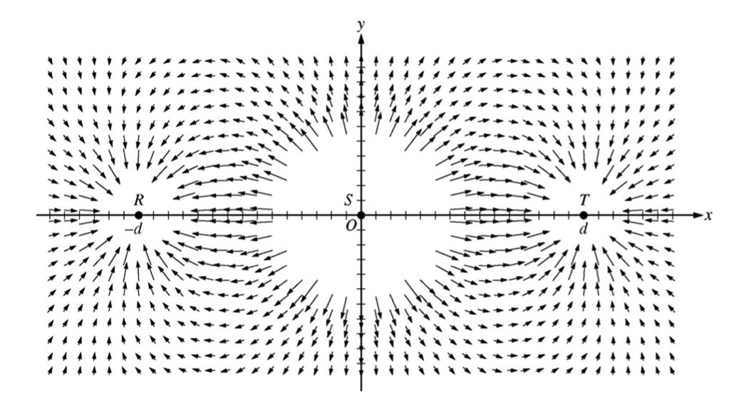
The figure above represents the electric field in the vicinity of three small charged objects, R, S, and T. e objects have charges -q, +2q, and -q , respectively, and are located on the x-axis at -d , 0, and d. Field vectors of very large magnitude are omitted for clarity.
(a)(i) Briefly describe the characteristics of the field diagram that indicate that the sign of the charges of objects R and T is negative and that the sign of the charge of object S is positive.
(ii) Briefly describe the characteristics of the field diagram that indicate that the magnitudes of the charges of objects R and T are equal and that the magnitude of the charge of object S is about twice that of objects R and T.
For the following parts, an electric field directed to the right is defined to be positive.
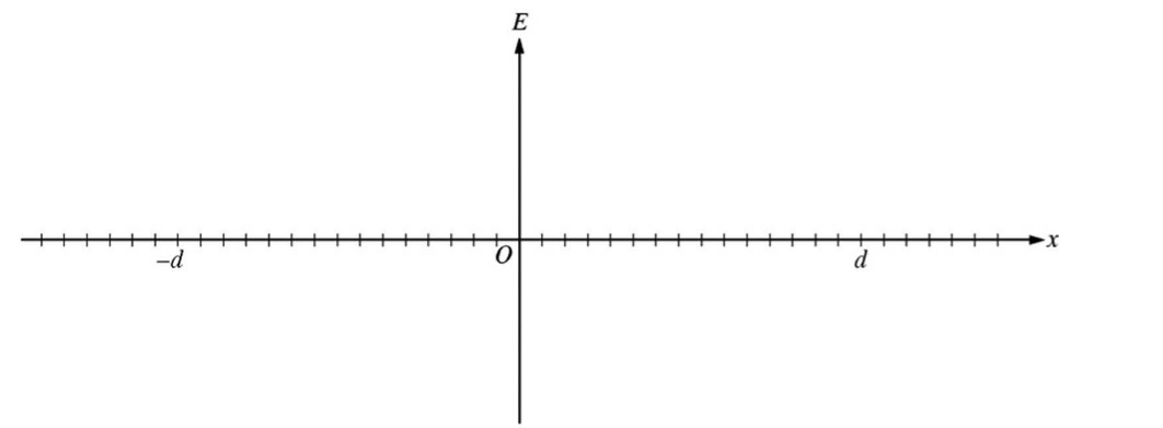
(b) On the axes below, sketch a graph of the electric field E along the x-axis as a function of position x.
(c) Write an expression for the electric field E along the x-axis as a function of position x in the region between objects S and T in terms of q, d, and fundamental constants, as appropriate.
(d) Your classmate tells you there is a point between S and T where the electric field is zero. Determine whether this statement is true, and explain your reasoning using two of the representations from parts (a), (b), or (c)
▶️Answer/Explanation
Ans:(a)
(i) For indicating that the direction of the field vectors is the telling characteristic and describing how they indicate negative and positive charge
Example: The direction of the field vectors. Field vectors near objects point toward negatively charged objects and away from positively charged objects.
(ii) For indicating that the size and distance of the closest field vectors are the telling characteristics
For describing how the size and distance of the closest field vectors indicate the magnitudes of the charges Field vectors nearest R and T are at about the same distance and have approximately the same length, so the magnitude of their charge is equal. Field vectors nearest S have approximately the same length as field vectors nearest R and T, but the square of the distance to the field vectors nearest S is about twice the square of the distance to the field vectors nearest R and T –36 (6 tic marks squared) compared with 16 (4 tic marks squared). So the
magnitude of the charge of S is twice the magnitude of the charges of R and T.
Example:
The vectors closest to R and T are about the same length and start at about the same distance \( q_R/d^2= q_T/d^2\) ,. so the charge on R is about the same as the charge on T. The closest vectors around S are about the same length as those around R and T. The vectors near S start at about 6 units away, while vectors near R and T start at about 4 units\( q_R/d^2= q_S/D^2\). so ,
\( q_S/q_R=D^2/d^2 \) and so the charge on S is about twice that on R and T.
(b) For showing reasonably close to asymptotic behavior on both sides of the charge positions
For a general U shape between the charges that does not touch the x-axis
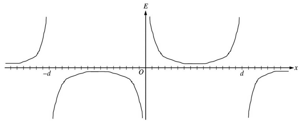
For all signs consistent with the vector map
The following shows a more exact plot. e scale is set to show the asymptotic behavior, which masks the nonzero values between charges and at both sides of the range.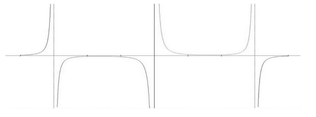
(c) For correctly associating charge values with positions
For using the correct sign and power in the expressions for the distance to each charge , For the correct sign for the direction of the field for each term 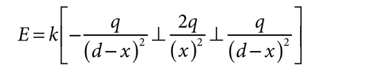
(d) For indicating that the value of the electric field is nonzero for all values between S and T
For justifying the above using one of the representations
For justifying the above using a second representation
The following are the ideas that should be expressed for each representation:
\(\blacksquare \) The vectors between S and T in the electric field diagram all have nonzero length
\(\blacksquare \) The graph between S and T never crosses the x-axis
\(\blacksquare \) The negative term of the equation in part (c) is either always smaller than the other terms in this region or never completely cancels them both
Example:
The statement is not true. e vector diagram shows field vectors in this region with nonzero length, and the vectors not shown have even greater lengths. The equation in part (c) shows that when the denominator of the negative term is always greater than the denominator of the third term, but the numerator is the same. So the negative term always has a smaller magnitude than the third term, and since the second term is positive, the sum of the terms is always positive. Note: A response claiming that there is a zero value can receive credit if it is consistent with an incorrect response in either part (b) or (c).
Question
Use the electric field drawing below to answer the questions. A, B, and C are physical sources of charge. Points e, d, and f are points within the field.
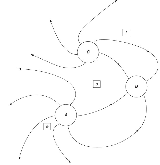
(a) Describe the relative amount of charge and type (positive or negative) at each of locations A, B, and C . Explain your answers.
(b) Rank the relative strength of the net electric field at each of points e, d, and f . Explain your answer.
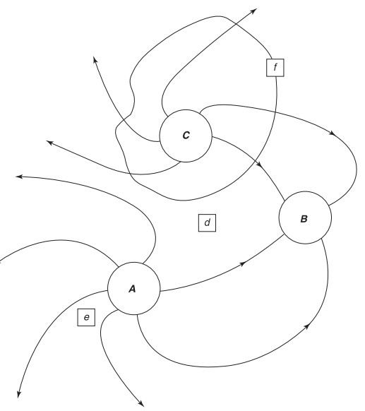
(c) By extending the existing sketch, sketch out what the field lines would look like from very far away from these charges. Assume no other charges are present.
(d) On the sketch above, draw a single, complete equipotential surface that runs through point f.
(e) How can there always be electric potential at point f and yet the electrical potential energy sometimes be zero?
(f) If a proton was placed at point f , in what direction (if any) would it experience a force? Would its change in electrical potential energy be negative or positive as it moved in response to this electrical force? Explain your reasoning.
(g) Repeat the answers to the questions in part (f) but for an electron placed at point e.
▶️Answer/Explanation
Ans:
(a) The number of field lines indicates the amount of charge. The direction of field lines indicates the type of charge:
amount of charge A (positive) > amount of charge C (positive) > amount of charge B (negative)
(b) The strength of the field is proportional to the density of the field lines:
field at e > field at f > field at d
(c) From very far away, the details of the actual charge distribution will not matter. The field will look like that of a positive point charge with the 7 unconnected field lines coming out uniformly.
(d) Equipotential lines should intersect electric field lines perpendicularly, do not have direction, and are continuous.
(e) Electric potential comes from the source charge and does not require a test charge to be present in the field. Electrical potential energy exists only if there is a test charge present within the field: EPE = qV .
(f) A proton would follow the field direction at its location, so up and to the right at point f . Positive charges go from high voltage to low voltage:
ΔV < 0, so qΔV < 0
Electrical potential energy decreases while electrical potential decreases.
(g) Electrons will experience a force in the opposite direction from the field lines, so straight toward A at point e . Negative charges go from low voltage to high voltage:
ΔV > 0, so qΔV < 0
since q is negative. Electrical potential energy decreases while electrical potential increases.
Question: (10 points – suggested time 20 minutes)
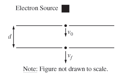
The apparatus shown in the figure above consists of two oppositely charged parallel conducting plates, each with area A = 0.25 m2 , separated by a distance d = 0.010 m . Each plate has a hole at its center through which electrons can pass. High velocity electrons produced by an electron source enter the top plate with speed v0 = 5.40 ×10⁶ m/s, take 1.49 ns to travel between the plates, and leave the bottom plate with speed vf = 8.02 ×10⁶ m/s .
(a) Which of the plates, top or bottom, is negatively charged? Support your answer with a reference to the direction of the electric field between the plates.
(b) Calculate the magnitude of the electric field between the plates.
(c) Calculate the magnitude of the charge on each plate.
(d) The electrons leave the bottom plate and enter the region inside the dashed box shown below, which contains a uniform magnetic field of magnitude B that is perpendicular to the page. The electrons then leave the magnetic field at point X.
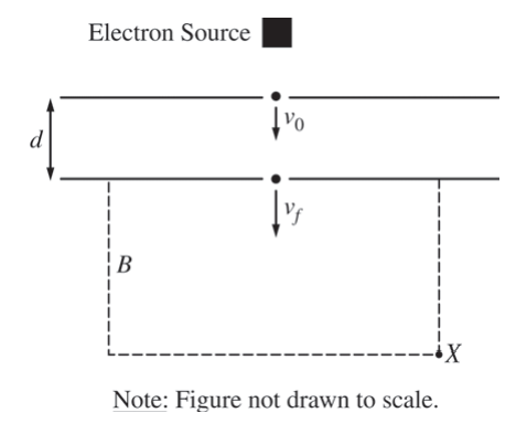
i. On the figure above, sketch the path of the electrons from the bottom plate to point X. Explain why the path has the shape that you sketched.
ii. Indicate whether the magnetic field is directed into the page or out of the page. Briefly explain your choice.
▶️Answer/Explanation
Ans:
The top plate is negatively charged. The electrons increase their speed, s their acceleration is downward. This means by F = ma, the electric force points downward. Since these are electrons, the force is in the opposite direction of the field lines, which thus point up. Field lines point towards the negative plate, which is the top one
W = ΔKE
Vg = ΔKE
Ed = \(\frac{\Delta KE}{g}\)
\(E = \frac{1}{2}\left ( \frac{1}{q} \Delta KE\right )\)
\(E = \left ( \frac{1}{0.010m} \right )\left ( \frac{1}{1.6\times 10^{-19}C} \right )\left ( \frac{1}{2} \right )\left ( 9.11\times 10^{-31}Kg \right )\left ( (8.02\times 10^{6}m/s)^{2}-(5.40\times 10^{6}m/s)^{2} \right )=1.0\times 10^{4}N/C\)
(c)
\(C = \frac{\varepsilon .A}{d}\)
\(\frac{Q}{V} = \frac{\varepsilon .A}{d}\)
\(Q = \frac{\varepsilon 0EdA}{d} = \varepsilon 0EA\)
= (8.85 × 10⁻¹² C2/Nm2) (1.0×10⁴N/C) (0.25m2) = 2.2×10⁻⁸C
(d)
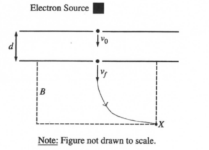
i.
The magnetic force is always perpendicular to the direction of velocity. Thus, the force acts as a centripetal force, so the electrons undergo circular motion.
ii.
The magnetic field is directed out of the page. By the right hand rule (force to the right, velocity down,) the magnetic field is into the page. Since the electrons are negatively charged, we switch the direction so the field is out of the page (the right hand rule applies to positively charged particles.)