Question:(10 points-suggested time 20 minutes)
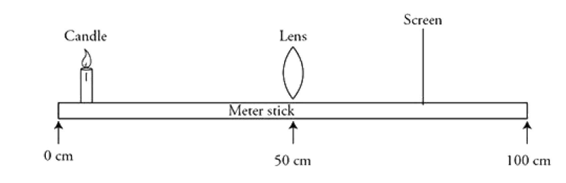
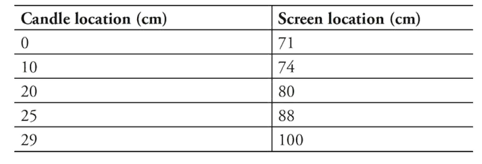
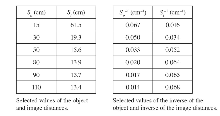
In a laboratory experiment, an optics bench consisting of a meter stick, a candle, a lens, and a screen is used, as shown in the figure. A converging lens is placed at the 50-cm mark of the meter stick. The candle is placed at various locations to the left of the lens. The screen is adjusted on the right side of the lens to produce a crisp image. The candle and screen locations on the meter stick produced in this lab are given in the table. Extra columns are provided for calculations if needed.
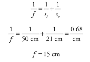
(A) Calculate the focal length of the lens. Show your work.
(B) Use the data to produce a straight line graph that can be used to determine the focal length of the lens. Calculate the focal length of the lens using this graph and explain how you found the focal length from the graph.

(C) Sketch a ray diagram to show how the candle would produce an upright image with a magnification larger than 1.0. Draw the object, at least two light rays, and the image. Indicate the locations of the focus on both sides of the lens.
(D) A student says that virtual images can be projected on a screen. Do you agree with this claim? How could you perform a demonstration to support your stance with evidence?
▶️Answer/Explanation
Ans:
Part (A)
1 point-For correctly calculating an appropriate set of image and object distances.
For example: Knowing that the lens is located at 50 cm and using the first set of data, we get the following:
s0 = 50 cm – 0 cm= 50 cm
si = 71 cm – 50 cm = 21 cm
1 point-For correctly calculating the focal length of the lens:
Part (B)
1 point-For explaining how to produce a straight line from the data and why they-intercept equals 1/f.
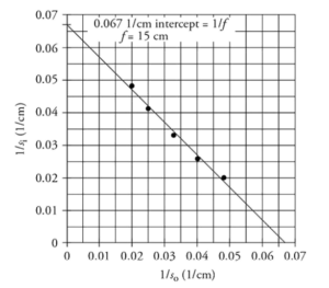
1 point-For plotting 1/s0 on the x-axis and 1/si on the y-axis and drawing a best fit line through the data.
1 point-For calculating the correct focal length using they-intercept.
Example: The lens equation can be rearranged to produce a straight line:
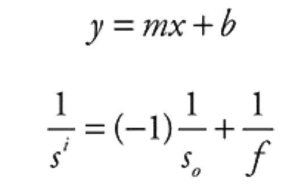
Thus, if we plot l/s0 on the x-axis and l/si on the y-axis, we should get a graph with a slope of -1 and an intercept of 1/f.
From our graph, the intercept is 0.067 1/cm, which gives us a focal length of 15 cm (the same as part A).
Part (C)
1 point-For drawing the candle or other object between the focus and the lens. This point cannot be awarded if the focal points are not designated on the drawing.
1 point-For drawing two correct rays from the object and passing through the lens. This point cannot be awarded if the focal points are not designated on the drawing. However, the point can be earned even if the object is not correctly located between the focus and the lens as long as the rays are correct for the object and lens placement.
1 point-For drawing a correct virtual image. The image should be upright, located at the intersection of the two outgoing rays, and be larger than the object.
Here is an example drawing:
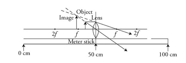
(An upright image will be virtual. The object will need to be between the lens and the focal point. Sketches will differ, and image locations will vary a bit depending on where the object is placed between the focal point and the lens.)
Part (D)
1 point-For disagreeing and stating that virtual images can be seen but cannot be projected on a screen.
1 point-For describing an appropriate demonstration to prove that virtual images cannot be projected on a screen.
For example: Produce a real image and show that it can be projected on a screen. Then create a virtual image and show that the image cannot be made to show up on the screen.
Question
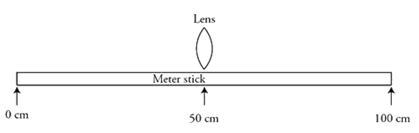
A student has a convex lens of unknown focal length. He lights a candle in a darkened room and uses the lens and moves a screen until he forms a sharp image. He then records the distance from the candle to the lens and the distance from the lens to the screen. Below is a sketch of his set-up and his data.
(a) Explain how a graph of 1/ s0 vs. 1/ si can be used to find the focal length of the lens.
(b) Create a graph of and find the focal length of the lens used in the experiment.
(c) Use ray tracing to make a sketch when the object is 6 cm from the lens.
(d) The top half of the lens is now covered by a sheet of cardboard so that light rays can only strike the bottom half of the lens. Briefly explain what effect this has on the image and how this would affect a ray tracing diagram.
▶️Answer/Explanation
Ans:
(a) \(\frac{1}{f}=\frac{1}{s_{i}}+\frac{1}{s_{0}},\) so a plot of s0 – 1 vs. si-1 will have a y-intercept which will be equal to \(\frac{1}{f}\)
(b) 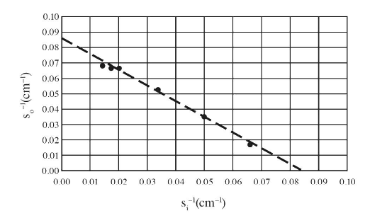
The y-intercept is approximately 0.083, so the focal length is \(\frac{1}{0.083cm^{-1}}=12 cm.\)
(c) The diagram needs to have a focal length of 12 cm and an object distance of 6 cm.
( d) The brightness of the image would decrease but the location of the image would not change. The ray diagram would require using rays that are not the principle rays as all three principle rays are blocked. However, all rays coming from the object converge at the image position, so the image position would not change.
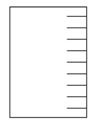
Question: (12 points, suggested time 25 minutes)
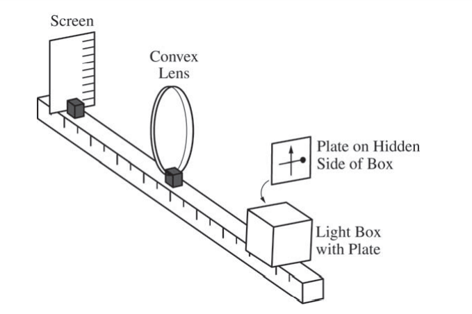
Some students are asked to determine the focal length of a convex lens. They have the equipment shown above, which includes a waterproof light box with a plate on one side, a lens, and a screen. The box has a bright light inside, and the plate on the side has shapes cut out of it through which the light shines to create a bright object. This particular plate has a cutout that is a vertical arrow and a horizontal bar with a circle at one end. In the view shown above, the circle is near the right edge of the plate. With the screen and light box on opposite sides of the lens, the box is aligned so that the plate is 20 cm from the center of the lens, and an image of the arrow and bar is formed on the screen. The students find that the image is clear on the screen when the screen is 30 cm from the center of the lens.
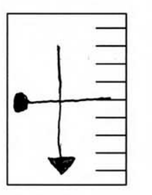
(a) On the figure below, sketch how the image on the screen appears to the students.
(b)
i. Calculate the focal length of the lens.
ii. Calculate the magnitude of the magnification of the image.
(c)
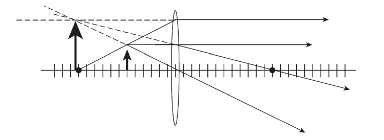
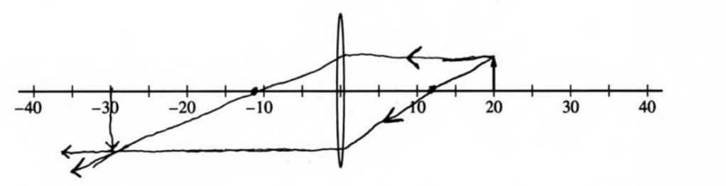
i. In the side view below, the arrow represents the bright object created by the plate. Draw a ray diagram on the figure below that is consistent with your calculations in parts (b)(i) and (ii). Show at least two rays, as well as the location and orientation of the image.
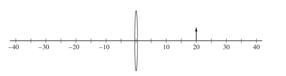
ii. Explain how your diagram is consistent with your calculated focal length and magnification in parts (b)(i) and (ii).
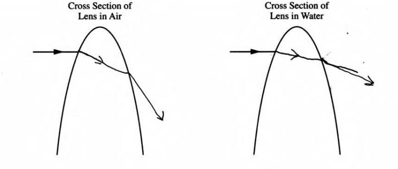
(d) The entire apparatus is now submerged in water, whose index of refraction is greater than that of air but less than that of the lens.
i. The figures below show cross sections of the top portion of the convex lens in air and the convex lens in water. An incident ray is shown in both cases. On each figure, draw the ray as it passes through the lens and back into the air or water.
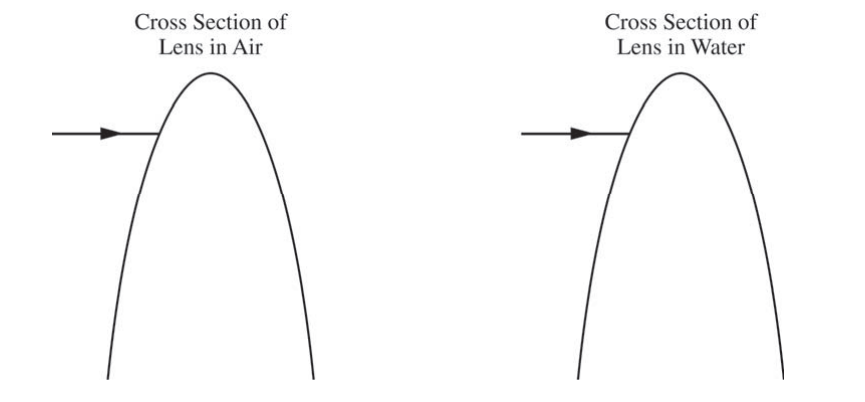
ii. Describe how the focal length of the lens and the position and size of the image formed by the lens when it is in the water compare to when the lens is in air. Explain how the rays drawn in the figures in part (d)(i) support your answer.
▶️Answer/Explanation
Ans:
(a)
(b)
i.
\(\frac{1}{s_{i}}+\frac{1}{s_{0}}=\frac{1}{f} \) \(\frac{1}{3Ccm}+\frac{1}{2Ccm}=\frac{1}{f}\) f = 12cm
ii.
\(M = \frac{s_{i}}{s_{0}}=\frac{3Ccm}{2Ccm}\)
\(M = \frac{3}{2}\)
(c) i.
ii.
By placing the focal points a distance that is 12 cm from the lense, the rays create an image that is \( \frac{3}{2}\) times the size of the object.
(d) i.
ii.
The focal length is longer when the apparatus is submerged. The image is also formed further away from the lense, and its magnification is greater. The rays from (d) (i) support this because the ray of the submerged apparatus bends less after entering the lens as opposed to the apparatus in the air. As a result, it will take a longer distance to intercept its focal point, meaning that the focal length is longer. If the focal points are further away, then that means that the ray from the object that intercepts the focal point, then enters the lens will have travelled further downwards before it reaches the lens. As a result, the magnified image will be larger.