Question
A gas with a ground state of -8.0 e V is illuminated by a broad ultraviolet spectrum of light and is found to absorb 248 nm of light. When the ultraviolet light is turned off, the gas sample emits three different. wavelengths of light: 248 nm, 400 run, and 650 nm.
(A) On the axis provided, construct and label an energy level diagram that displays the process of both the absorption and emissions by the gas. Show your supporting calculations below.
(B) The light emitted by the gas is directed toward a sample of tin. It is found that the 248-nm emission from the gas causes electrons to be ejected from the tin, but that the 400-mn emission does not. Will the 650-nm emission eject electrons from the tin? If so, explain how it could be accomplished. If not, explain why it is not possible.
(C) The light from the gas is now directed at a sample of potassium that subsequently ejects electrons with a maximum energy of 2.71 eV.
i. Calculate the de Broglie wavelength of the maximum energy electrons.
ii. These electrons are directed at two small openings spaced 2 nm apart. Will this result in the formation of an interference pattern?
Justify your answer using appropriate physics principles.
▶️Answer/Explanation
Ans:
Part (A)
There are two ways to construct this energy level diagram. Both are shown below.
For converting the wavelengths of light in energy in electron volts.
\(E=hf=\frac{hc}{\lambda}\)
248 nm= 5 eV, 400 nm= 3.1 eV, 650 nm= 1.9 eV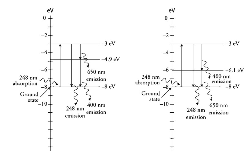
Part (B)
The 400 nm photon is below the threshold energy (work function) needed to eject an electron. The 650 nm photon has even less energy than the 400 nm photon.
Part (C)
(i) Electron kinetic energy= \((2.71eV)(1.6\times 10^{-19}J/eV)=4.34\times 10^{-19}J\)
\(K=\frac{1}{2}m_{0}v^{2}\)
\(v=\sqrt{\frac{2L}{m_{c}}}=9.76\times 10^{5}m/s\)
\(\lambda=\frac{h}{p}=\frac{h}{m_{c}v}=7.46\times 10^{-10}m\)
(ii) The electrons will form an interference pattern, as the waves are on the same order of magnitude and smaller than the opening spacing. The equation \(\sin\theta=\frac{m\lambda}{d}\) shows us that the ratio \(\frac{\lambda}{d}\) needs to be less than 1 for an interference pattern to form. Any larger ratio will cause the angle 0 to be larger than 90 degrees, and no pattern will form. This means the wavelength must be smaller than the spacing, but not too small or the angle will be so small that the pattern will be too small to see.
Question
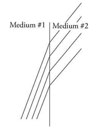
The figures show two different representations of the same plane wave traveling through medium #1 and approaching a boundary between two transparent media. The left figure shows a light ray representation. The right figure shows a wave front representation. The index of refraction of medium #1 is greater than that of medium #2.
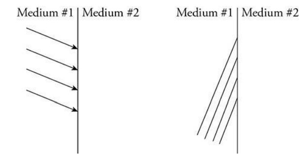
(A) i. On the left figure, complete the diagram by sketching the path of all four rays in medium #2.
ii. On the right figure, complete the diagram by sketching all four wave fronts in medium #2.
(B) The figure represents another series of plane waves traveling toward and incident on a barrier in its path. One wave model treats every point on a wave front as a point source.
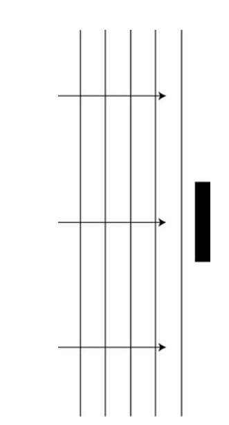
i. Use the point source model to help you sketch the wave as it passes the barrier.
ii. In a clear, coherent paragraph-length response, describe how this point source model explains the shape of the wave as it passes the barrier and why an interference pattern is produced beyond the barrier on the right.
(C) The figure represents another series of plane waves traveling toward and incident on a barrier with two identical openings.
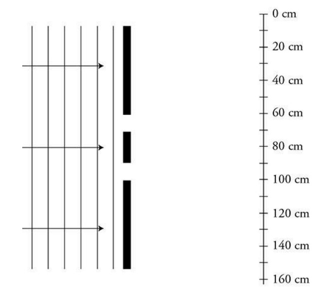
i. Sketch a representation of the interference pattern produced on the wall beyond the barrier. The wall is marked with centimeters for your reference. The 80-cm mark is aligned with the center of the barrier. Indicate locations of constructive interference with the letter C and locations of destructive interference with the letter D.
ii. The distance between the wave fronts is increased. How does this affect the interference pattern? Explain your answer.
▶️Answer/Explanation
Ans:
Part (A)
The left figure rays should all be parallel and pointing downward, with the angle of refraction larger than angle of incidence.
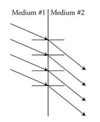
The right figure should also show the waves traveling in a more downward direction. All wave fronts should be parallel, and the wavelength between the wave fronts should be larger in medium #2.
Part (B)
The sketched waves should bend around the boundary and overlap in circular paths that maintain the same wavelength.
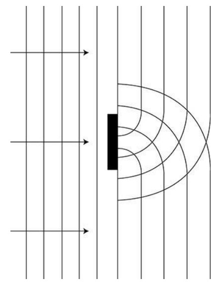
The point source model says that every point on the wave is the source of a new wavelet that propagates outward. For the plane waves approaching the barrier, the sum of all the wavelets produces another plane wave in front of the last one. The barrier blocks the center wavelets. The plane waves on either side of the boundary continue forward, but the wavelets on the end of the blocked wave produce curved waves that propagate inward to fill the central area beyond the boundary. These curved waves will overlap and form constructive interference, where crests meet crests and troughs meet troughs. They will create destructive interference where crests meet troughs.
Part (C)
There are several ways to draw this. The interference pattern could be drawn as alternating dark and light patches to show the constructive interference points as shown in this sample diagram. An amplitude function could also be used to represent the interference pattern. We do not have enough information to calculate the exact locations of the constructive and destructive interference. However, the patterns should be symmetrical about the center line (the 80-cm mark).
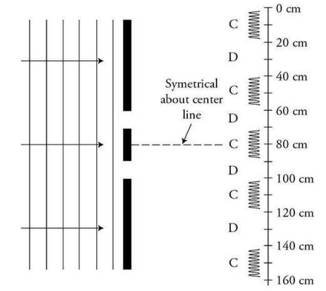
As the distance between the wave fronts is increased, the wavelength gets larger. This means the pattern will spread out as the angle 8 gets larger: d sin 8 = m2.
Question
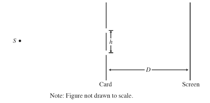
In a double-slit interference experiment, a parallel beam of monochromatic light is needed to illuminate two narrow parallel slits of width w that are a distance h apart, where h » w, in an opaque card as shown in the figure above. The interference pattern is formed on a screen a distance D from the slits, where D >> h.
(a) Draw the first three wave fronts that emerge from each slit after the card.
(b) In a clear, coherent, paragraph-length response, explain why a series of bright spots are seen on the screen after the light shines through the card.
(c) In the interference patterns on the screen, the distance from the central bright fringe to the third bright fringe on one side is measured to be y3. In terms of D, H, y3 and S,
what is the wavelength of the light emitted from the source S?
(d) If the space between the slits and the screen was filled with a material having an index of refraction n > 1, would the distance between the bright fringes increase, decrease, or remain the same? Explain your reasoning.
▶️Answer/Explanation
Ans:
(a) 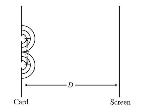
(b) The double slit experiment works by producing coherent spherical wave fronts that interfere with one another. A spherical wave front is produced when a plane wave impinges upon a small slit, such as either of the slits in the card, as shown in part (a). The two spherical wave fronts then propagate to the screen and because there are two waves, they interfere with one another. Bright spots occur whenever there is constructive interference and dark spots indicate that the interference is destructive. The interference will be constructive whenever the difference in the distance that the two waves travel is an integer multiple of the wavelength of the initial plane wave. There will be bright spots when the difference in travelled distance is o (in the middle), or ±1 wavelength, etc. There are a series of bright spots because there are many different possible locations on the card where constructive interference occurs.
(c) In the double slit experiment mA = dx/L. Solving for A
\(\lambda = \frac{dx}{Lm}\)
d is the distance between the slits, x is the distance measured between fringes, L is the space from the slits to the screen and m is the “order” or the number of dark spots between fringes. Using the given variables,
\(\lambda = \frac{hy_{3}}{3D}\)
(d) When light enters a medium with a different index of refraction, its speed changes. The light wave will have a constant frequency, so this results from a change in its
wavelength. When light goes from an index of n = 1 to an index of n > 1, the wave speed decreases, resulting in a decreased wavelength.
\(\lambda = \frac{dx}{Lm}\)
So x is directly proportional to l, and the distance between fringes will decrease.