Question
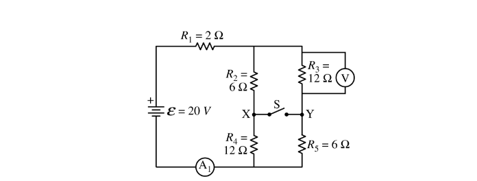
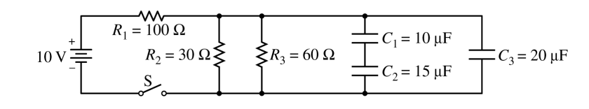
A circuit is created with an ideal battery and five resistors with the values shown in the figure above. An open switch is shown that can connect points X and Y. A voltmeter V and an ammeter \(A_1\) are also shown in the figure.
(a) The switch is in the open position.
i. Calculate the current measured by the ammeter \(A_1\) .
ii. Calculate the potential difference measured by the voltmeter V.
(b) The switch is now moved to the closed position.
i. Calculate the current measured by the ammeter\ (A_1\) .
ii. Calculate the potential difference measured by the voltmeter V.
A student wants to determine if there is a current in the closed switch. The switch is now replaced with ammeter \(A_2\) between points X and Y. The ammeter acts as a closed switch and can measure the current, if any, between the two points.
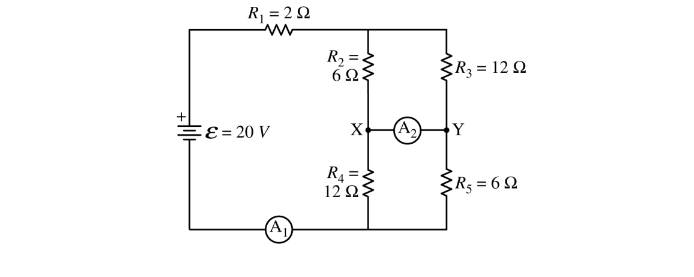
(c)
i. Calculate the current measured by ammeter\( A_2\) .
ii. Indicate the direction of the current, if any, through the ammeter\( A_2\) .
Left______ Right_________ Undefined, because the current is zero
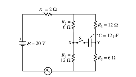
(d) The ammeter A_2 is replaced with switch S and capacitor C = 12 Fμ , as shown in the figure above. Switch S is closed.
i. Calculate the charge stored on the positive plate of capacitor C a long time after switch S is closed.
ii. Which point, X or Y, is at a higher electric potential? X Y Justify your answer.
Answer/Explanation
(a)(i)
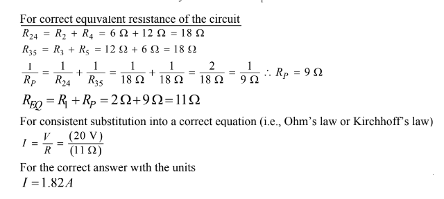
(ii) For correct substitution (consistent with a(i)) into a correct equation to calculate the potential difference across \(R_3\) \(V_p = \varepsilon − V_1 = \varepsilon − IR_1 = (20 V) – (1.82 A)(2 \Omega ) = 16.4 V\) \(I_{35}=\frac{V_p}{R_{35}}=\frac{ (16.4 V)}{ (18)}= 0.91 A\) \(V_3=I_{35}R_3=(0.91 A)(12 \Omega ) = 10.9 V\)
b.(i)
For the correct equivalent resistance of the circuit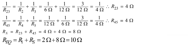
For consistent substitution into a correct equation (i.e., Ohm’s law or Kirchhoff’s law)
\(I=\frac{v}{r} \rightarrow \frac{20}{10}=2A\)
(ii)
For correct substitution (consistent with b(i) ) into a correct equation to calculate the potential difference across \(R_3\)
\(V_3=I_{35}R_3=(2 A)(4 \Omega ) = 8 V\)
(c)
i)
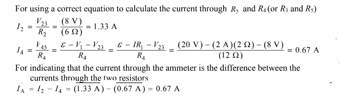
ii) For selecting “Right” Note: If a student calculated IA in Part c(i) to be zero then the consistent answer of “Undefined” earns 1 point.
(d) i)
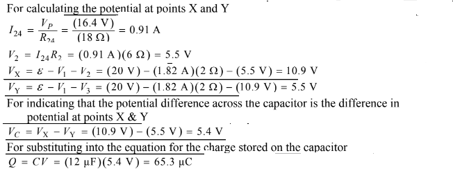
ii) Selecting “X” For a correct justification Example: The point X is at higher potential because the current flows to the right. The current flows from high potential to low potential.
Example: The potential at X is 10.9 V and the potential at Y is 5.5 V. So point X is at the higher potential.
Question
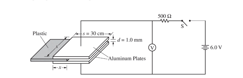
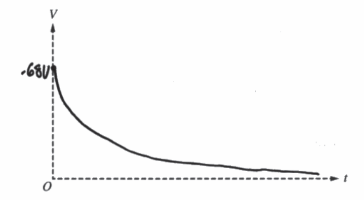
Students design an experiment to determine the unknown dielectric constant k of a plastic material. A capacitor is created using two square aluminum plates of side length s = 30 cm that are separated by a distance d = 1.0 mm. This capacitor is placed in a circuit with an ideal 6.0-volt battery, a resistor of resistance R = 500 W , voltmeter V, and an open switch S, as shown above. A 1.0 mm thick piece of plastic is inserted between the aluminum plates. The distance x that the plastic is inserted between the plates can be varied, and the voltmeter is used to measure the potential difference \(V_C\) across the capacitor. The switch is closed, and readings from the voltmeter are recorded as a function of time t. The data are plotted to create the graph shown below.
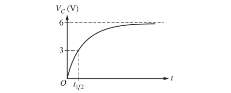
The time \(t_{1/ 2}\) shown above is the time for the capacitor to charge to half the potential difference of the battery.
(a) The potential difference across the capacitor as a function of time is modeled by the equation \(V_c=V_{Max}(1-e^{-t/RC})\),where \(V_{Max}=6V\). Derive an expression for the capacitance C of the capacitor. Express your answer in terms of \(t_{1/ 2}\) , R, and physical constants, as appropriate. The data for x and\(t_{1/ 2}\) are recorded for several trials and the value of C for each trial is calculated. The results are shown in the chart below.

(b) Plot the experimental value of the capacitance C as a function of the distance x on the graph below. Clearly scale and label all axes, including units if appropriate. Draw a straight line that best represents the data.

(c) The capacitor in the lab can be treated as two capacitors in parallel, one with the dielectric and one with air between the plates. Show that the capacitance can be expressed as \(C=\frac{\varepsilon _{0}s}{d}(s+x(k-1))\).
(d) Using the graph from part (b), calculate the value of the dielectric constant k .
(e) The students now want to verify the value for the permittivity constant,\( \varepsilon _0 \). Using the graph from part (b), calculate an experimental value for \(\varepsilon _0\) .
(f) Assume the value found in part (e) is higher than the accepted value for the permittivity constant. State one possible physical reason for this error and explain how it could have caused this error.
Answer/Explanation
(a) For correctly substituting into given equation
\(V_c=6(1-6^{-6/RC})\therefore 3=6(1-e^{-t_{1}/RC})\)
For correctly solving the above equation
\(\frac{3}{6}=1-e^{-t_{1}/RC})\therefore e ^{t_{\frac{1}{2}}/RC}=\frac{1}{2}\therefore -t_{\frac{1}{2}}/RC=ln(\frac{1}{2})\)
\(C=\frac{t_{\frac{1}{2}}}{R ln(2)}\)
Note: Answer point is earned with or without a negative sign
(b) For using a correct scale that uses more than half the grid and for correctly labeling the axes including units as appropriate For correctly plotting the data For drawing a straight line consistent with the plotted data
(c) For indicating that the capacitance is equal to the sum of the part with a dielectric and the part with air \(C = C_x + C_o \)For correctly substituting for the part of the capacitor that has a dielectric For correctly substituting for the part of the capacitor that has air \(C =\frac{KEOSX}{d}+\frac{\varepsilon _OS (s – x)} {d}(Kx+s-x)=\varepsilon_ {O}S{d} (s + x(k − 1))\)
(e) For using an acceptable value for the y-intercept consistent with the best-fit line For correctly relating the y-intercept to the permittivity constant \(C=\frac{\varepsilon _0s^2}{d}+\frac{\varepsilon _0s(k-1)}{d}x\therefore y -intercept=\frac{\varepsilon _0s^2}{d}
\varepsilon _0=\frac{(d)(y -intercept)}{s^2}=\frac{\left ( 1\times 10^{-3}m \right )\left ( 8.4\times 10^{-10}F \right )}{(.3m)^2}=9.29\times 10^{-12}C^2/(N.M^2)\)
(f) For a correct explanation of an acceptable physical issue Claim: The resistance in the wires would cause the experimental value to be higher than the accepted value of the permittivity constant.
Evidence: The potential difference across the capacitor would be smaller.
Reasoning: The wires could have nonnegligible resistance.
Alternate Explanation
Claim: The air between the plates of the capacitor would cause the experimental value to be higher than the accepted value of the permittivity constant.
Evidence: The air between the plates of the capacitor increases its capacitance.
Reasoning: The air between the plates of the capacitor act as a dielectric.
Question
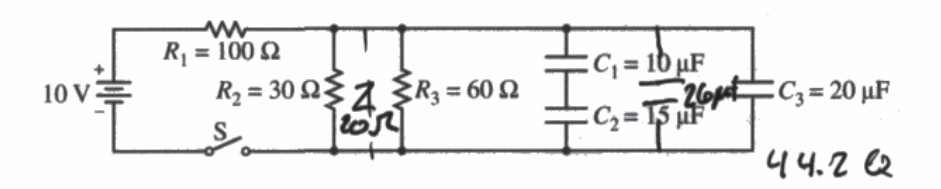
The circuit shown above is composed of an ideal 10 V battery, three resistors and three capacitors with the values shown, and an open switch S. . The capacitors are initially uncharged. Switch S is now closed.
(a) Calculate the current through R1 immediately after switch S is closed.
Switch S has been closed for a long time, and the circuit has reached a steady state.
(b) Calculate the potential difference across R1.
(c)
i. Calculate the charge stored on the positive plate of capacitor C2.
ii. Is the charge stored on capacitor C3 greater than, less than, or equal to the charge stored on capacitor C2 ?
_____Greater than _____ Less than _____ Equal to
Justify your answer
Switch S is then opened.
(d)
i. Determine the current through R1 immediately after the switch is opened.
ii. Calculate the current through R2 immediately after the switch is opened.
(e) On the axes below, sketch a graph of the potential difference V across capacitor C2 as a function of time t if switch S is opened at time t = 0. Label the maximum value.
Capacitor C3 is replaced by two 10 μF capacitors connected in series, switch S is closed, and the circuit reaches equilibrium. Switch S is then opened at time t = 0.
(f) For t > 0, would the sketch of a graph of the new voltage across C2 as a function of time be above, below, or the same as the sketch for part (e) ?
_____ Above _____ Below _____ The same
Justify your answer.
Answer/Explanation
Ans:
(a)
V = IR
10 V = I · 100 Ω I = .1A
(b)
V = If R If = .093 100 · .083 = V
10 V = U 120 Ω V = 8.3 V
(c) i.
\(\left ( \frac{1}{C_{1}}+\frac{4}{C_{2}} \right )^{-1}=C_{T}\) \(10 – 8.3 = \frac{Q}{C}\) 10.2 MC = Q
CT = CoμF \(1.7 = \frac{Q}{C_{0}\mu F}\)
ii.
__X___ Greater than
\(20\cdot 1.7 = \frac{Q}{20\mu}\cdot 20\) Q = 34net
because the voltage Orap B equal between parallel wires and C3 has to higher capacitor Q B also longer.
(d) i.
OA
ii.
V = IR
1.7V = I·30 I = .057A
(e)
(f)
__X___ The same
because two 10μF capacitors out the same as one 20μF capacitor.