Question
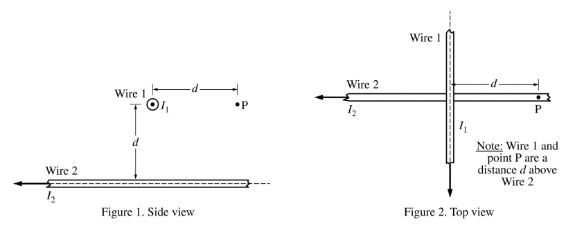
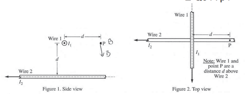
The figures above represent different views of two long, straight, horizontal wires, 1 and 2, carrying currents I1 = I and I2 = 2I , respectively, in the directions shown. The wires are held in place. In Figure 1, the current in wire 1 is directed out of the page, and wire 1 is a distance d above wire 2. Point P is a horizontal distance d from wire 1 and a distance d directly above wire 2. Express your answers to parts (a) and (b) in terms of I, d, and physical constants, as appropriate.
(a) Use Ampere’s law to derive an expression for the magnitude of the magnetic field at point P due to wire 1.
(b) Derive an expression for the magnitude of the net magnetic field at point P.
(c) Calculate the numerical value of the angle to the horizontal for the direction of the net magnetic field at point P.
(d) Wire 1 is now released. Which of the following best describes the initial motion of wire 1 due to the magnetic field of wire 2 ? Assume gravitational effects are negligible.
____ Wire 1 will not move.
____ Wire 1 will move upward as viewed in Figure 1.
____ Wire 1 will move downward as viewed in Figure 1.
____ Wire 1 will rotate clockwise as viewed in Figure 2.
____ Wire 1 will rotate counterclockwise as viewed in Figure 2.
Justify your answer.
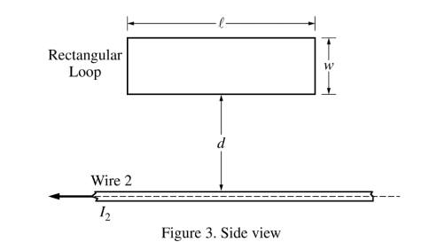
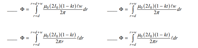
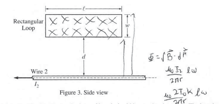
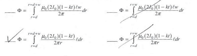
Wire 1 is now replaced by a conducting rectangular loop of length l, width w, and resistance R. The loop is placed a distance d from wire 2, as shown. The loop, wire, and distance d are all in the plane of the page. The long side of the loop is parallel to the wire. The current I2 for wire 2 is decreasing linearly as a function of time t according to the equation I2 = 2I0 (1 − kt), where k is a positive constant with units of s-1. (e) Of the following, select the integration that will give an expression for the flux Φ as a function of time t .
(f) Given that the flux through the rectangular loop as a function of time t is given by the equation \(\Phi =\frac{\mu _{0}I_{0}l(1-kt)}{\pi }In\left ( \frac{d+w}{d} \right )\) , derive an expression for the magnitude of the current, if any, induced in the loop. Express your answers in terms of I0 , d, r, R, w, k, l, and physical constants, as appropriate.
(g) What is the direction of the current, if any, induced in the loop as seen in Figure 3 ?
____ Clockwise ____ Counterclockwise
____ Undefined, because there is no current induced in the loop
Justify your answer.
Answer/Explanation
Ans:
(a)
Ampere’s Law
\(B = \frac{\mu _{0}I}{2\pi r}\) \(\overrightarrow{B} = \frac{\mu _{0}I_{1}}{2\pi d} = \frac{\mu _{0}I}{2\pi d}\)
(b)
\(\overrightarrow{B}_{2} = \frac{\mu _{0}I_{2}}{2\pi d}\) \(\overrightarrow{B}_{1} = \frac{\mu _{0}I_{1}}{2\pi d} \) \(\overrightarrow{B}_{net} = \frac{\mu _{0}}{2\pi d}\sqrt{4I^{2}+I^{2}}=\frac{\mu _{0}}{2\pi d} \sqrt{5}\)
\(\overrightarrow{B}_{net} = \sqrt{\overrightarrow{B_{1}}+\overrightarrow{B_{2}}} =\sqrt{\frac{{\mu _{0}}^{2}{I_{2}}^{2}}{4\pi^{2} d^{2}}+\frac{{\mu _{0}}^{}{I_{1}}^{2}}{4\pi^{2} d^{2}}}=\sqrt{\frac{{\mu _{0}}^{2}\left ( {I_{0}}^{2}+{I_{1}}^{2} \right )}{4\pi^{2} d^{2}}}=\frac{\mu _{0}}{2\pi d}\frac{\pi }{\sqrt{{I_{2}}^{2}+{I_{1}}^{2}}}\)
(c)
\(Tan\theta =\frac{\overrightarrow{B_{1}}}{\overrightarrow{B_{2}}}=\frac{\frac{M_{0}I}{2\pi d}}{\frac{\mu _{0}2I}{2\pi d}}= \frac{1}{2}\)
\(tan^{-1}\left ( \frac{1}{2} \right )= \theta 0\)
θ = 26.560
(d)
__√_ Wire 1 will not move.
According to the right hand rule, the magnetic field created by wire 2 will be into the page, which means \(\overrightarrow{B_{2}}\) is parallel to wire 1. Since \(\overrightarrow{F}=\overrightarrow{I}l_{x}\overrightarrow{B}\) , the fire willl be zero as B & I are parallel.
(e)
(f)
\(I = \frac{\varepsilon }{R}\) \(I = \frac{-d\Phi }{dt}=\frac{m_{0}I_{0}lK}{\pi }ln\left ( \frac{d+w}{a} \right )\)
\(I = \frac{m_{0}I_{0}lK}{\pi R }ln\left ( \frac{d+w}{a} \right )\)
(g)
_√___ Clockwise
According to the equation above, \(\) , As to me goes on, Φ decreases. According to the right hand rule, wire 2 creates a \(\Phi = \frac{m_{0}I_{0}l(1-kt)}{\pi }lnln\left ( \frac{d+w}{a} \right )\) Field into the page (X). This means that because the flux is decreasing and the area stays the same. \(\overrightarrow{B}\) into the page must be decreasing. In order to oppose this change in flux, Lenz’s law states thats a magnetic field will be created by an induced current. To compensate for the decrease in \(\overrightarrow{B}\) into the page, the current must run clockwise to create a \(\overrightarrow{B}\) into the page.
Question
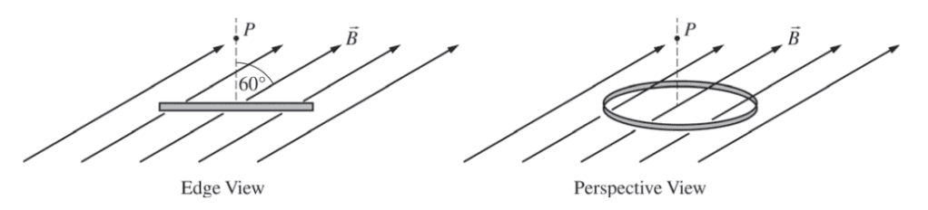
A circular wire loop with radius 0.10 m and resistance 50 Ω is held in place horizontally in a magnetic field \(\overrightarrow{B}\) directed upward at an angle of 60° with the vertical, as shown in the figure above. The magnetic field in the direction shown is given as a function of time t by B(t) = a(1- bt), where a = 4.0 T and b = 0.20 s-1 .
(a) Derive an expression for the magnetic flux through the loop as a function of time t.
(b) Calculate the numerical value of the induced emf in the loop.
(c)
i. Calculate the numerical value of the induced current in the loop.
ii. What is the direction of the induced current in the loop as viewed from point P ?
____ Clockwise ____ Counterclockwise
Justify your answer.
(d) Assuming the loop stays in its current position, calculate the energy dissipated in the loop in 4.0 seconds.
(e) Indicate whether the net magnetic force and net magnetic torque on the loop are zero or nonzero while the loop is in the magnetic field.
Net magnetic force: ____ Zero ____ Nonzero
Net magnetic torque: ____ Zero ____ Nonzero
Justify both of your answers.
Answer/Explanation
Ans:
(a)
Φm = ∫B.dA = (a) (1-bt) (πr2) (cos 600)
= \(\frac{1}{2}a(1-bt)(\pi )(0.01)=\frac{a\pi (1-bt)}{200}\)
(b)
\(\varepsilon =\frac{-d\phi m}{dt}=\frac{(-b)(a\pi )}{200}=\frac{ba\pi }{200}=\frac{0.2(4)\pi }{200}=12.6mV\)
(c) (i)
\(\varepsilon = IR\)
\(I = \frac{\varepsilon }{R}= \frac{0.0126V}{50\Omega }=0.251 mA\)
(ii)
ii. What is the direction of the induced current in the loop as viewed from point P ?
____ Clockwise ___×_ Counterclockwise
B is decreasing based on its function. By Jeny’s law the emp opposes the change in flux. By the right- hand rule the current flows counterclockwise to induce a magnetic field out of the page, in the directions of B.
(d)
\(E = Pt = \left ( \varepsilon ^{2}/R \right )t = \frac{.0126^{2}}{50}(4)= 1.27\times 10^{-5}J\)
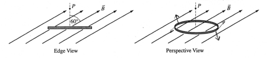
(e) Indicate whether the net magnetic force and net magnetic torque on the loop are zero or nonzero while the loop is in the magnetic field.
Net magnetic force: __×__ Zero ____ Nonzero
Net magnetic torque: ____ Zero __×__ Nonzero
F = Il × B
By the right hand rule, the direction of induced current results in an upward-left force on the left side of the loop and a down ward-right force of equal magnitude on the right side. The sum of these forces is zero but they rotate the loop around its arise by providing a tongue.
Question
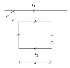
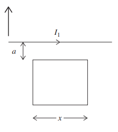
A very long wire carries current I1 . Nearby, a square wire loop of side x carries a current I2, which is produced by a very small battery within the loop as shown. The top side of the square
loop is located a distance a from the long wire.
(a) i. In terms of given variables and fundamental constants, calculate the magnitude of the total force applied by the long wire on the wire loop.
ii. Draw a vector indicating the direction of the magnetic force calculated in (a) i.
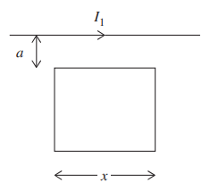
Now the battery in the square loop is removed, and the loop is placed at the same location. For the following, use values a = 0.02 m, x = 0.05 m, and I1 = 0.50 A.
(b) Calculate the magnetic flux through the square loop.
(c) Calculate the induced current in the square loop.
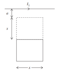
(d) Finally, the square loop is moved from its initial position to a new position, a distance a + x from the long wire. It takes 2 s for the wire to change locations. Using the values I1 = 0.50 A,
a = 0.020 m, and x = 0.050 m, calculate the average EMF induced in the square loop while it changes positions.
Answer/Explanation
(a)i. The magnetic field produced by I1 at the location of the wire loop is always into the page, by the right-hand rule associated with \(B=\frac{\mu _{0}I}{2\pi d}\). Thus, by the right-hand
rule associated with F = ILB, the force on the left-hand side of the loop is to the left; the force on the right-hand side of the loop is to the right. These forces are equal
in magnitude, because each element of the loop is the same distance from the long wire. So the side forces cancel.
The force on the top wire is upward and equal to I2 x B, where \(B=\frac{\mu _{0}I_{1}}{2\pi a}\). The force on the bottom wire is downward and equal to I2 x B, where \(B=\frac{\mu _{0}I_{1}}{2\pi (a+x)}\).
Subtract the two forces to get \(F=I_{2}\times \frac{\mu _{0}I_{1}}{2\pi a}-I_{2}\times \frac{\mu _{0}I_{1}}{2\pi (x+a)}\)
ii.
Now the battery in the square loop is removed, and the loop is placed at the same location.
(b) Here replace B with \(B=\frac{\mu _{0}I_{1}}{2\pi r}\) nd dA with x∙dr, where r is a variable representing distance from the long wire: \(x\int_{a}^{x+a}\frac{\mu _{0}I_{1}}{2\pi r}dr\). Take the integral to get \(\frac{\mu _{0}I_{1}}{2\pi }ln \ r,\) evaluated from a to x + a. That’s \(\frac{x \mu _{0}I_{1}}{2\pi }ln\left ( \frac{x+a}{a} \right )\). Any form of answer is acceptable, as long as the integral is actually evaluated—no integral notation on the final answer.
(c) This flux does not change in time, because the field and the area of the loop that the field penetrates don’t change in time. So zero induced current.

(d) Finally, the square loop is moved from its initial position to a new position, a distance a + x from the long wire. It takes 2 s for the wire to change locations. Using the values
I1 = 0.50 A, a = 0.020 m, and x = 0.050 m, calculate the average EMF induced in the square loop while it changes positions. Using the solution in (c), we know the
initial magnetic flux. Plugging into the result, the \(x\frac{\mu _{0}I_{1}}{2\pi}\) term gives 5.0 × 10⁻⁹ in standard units. The natural log term becomes ln (7/2) = 1.3.
So the initial flux is 6.3 × 10⁻⁹ Tm2. The final flux is calculated using the same formula, just plugging in the different locations of the loop: x + x + a and x + a. That’s
0.12 m and 0.07 m. The natural log term this time becomes ln (12/7) = 0.53. So the final flux is 2.7 × 10⁻⁹ Tm2.
Subtract final minus initial flux to get the change in flux of 3.6 × 10⁻⁹Tm2. But induced emf is change in flux divided by the time interval over which the flux
changed—divide by 2 s to get the final answer: the induced emf is 1.8 × 10⁻⁹ V (i.e., 1.8 nV).