Question
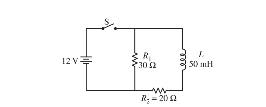
The circuit shown above is constructed using an ideal 12 V battery, an ideal switch S, and two resistors and an inductor with the values shown. Switch S is closed. After a long time, the circuit reaches steady-state conditions.
(a) Calculate the current through \(R_1\) .
(b) Calculate the current through the battery.
The switch is then opened at time t = 0.
(c) Determine the current in the inductor immediately after the switch is opened.
(d) i. Determine the current in resistor\( R_1\) immediately after the switch is opened.
ii. Which of the following statements is correct about the current through \(R_1\) immediately after the switch
is opened? _____ The current is up through \(R_1\) . _____ The current is down through \(R_1 \). _____ There is no current through \(R_1 \). Justify your answer.
(e) Immediately after the switch is opened, is the top end or bottom end of the inductor at the higher electric potential? ____ Top end ____ Bottom end Justify your answer.
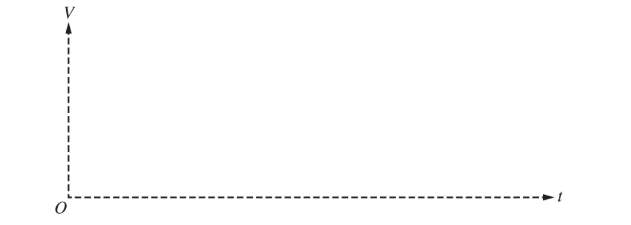
(f) On the axes below, sketch a graph of the potential difference V across the inductor as a function of time after the switch is opened. Explicitly label the vertical axis intercept with a numerical value.
(g) Write but DO NOT solve a differential equation that could be solved for the current through the inductor as a function of time after the switch is opened.
Answer/Explanation
(a) For using Ohm’s law to calculate the current\( I=\frac{V_1}{R_{1}}=\frac{12V}{30\Omega }\) For a correct answer I = 0.40 A
(b) For correctly calculating the equivalent resistance of the circuit \(\frac{1}{R_{T}}=\frac{1}{R_{1}}+\frac{1}{R_{2}}=\frac{1}{30\Omega }+\frac{1}{20\Omega }R_{T}=12\Omega\)
For using Ohm’s law to calculate the current \(I=\frac{V}{R_{T}}=\frac{12V}{12\Omega }=1.0A\)
(c) For an answer consistent with parts (a) and (b)\( I=I_2=\frac{12V}{20\Omega }=0.60A\)
(d) i. For an answer consistent with part (c)
\( I_1 I_2 = 0.60 A\) Note: Credit is earned even if no work is shown
ii. Selecting “The current is up through R1 .” 1 point For a correct justification including inductors resisting changes in current Example Justification: Conventional current would be going down through the inductor before the switch is opened. Inductors resists changes in current, so when the switch is opened, the current would continue to be down through the inductor and up
through\( R_1\) . Note: If wrong selection is made, the justification is ignored.
(e) Select “Bottom end” or an answer consistent with part (d)(ii) For a relating the direction of the current/emf to the end of the inductor that is at the higher electric potential Example Justification: The inductor will maintain a current going down through the inductor. Since conventional current comes out of the higher potential side, the bottom end of the inductor must be at the higher potential.
(f) For a concave up curve in the first quadrant For a curve that has an asymptote at the horizontal axis For correctly indicating the maximum value
(g) For correctly applying Kirchoff’s loop rule to the circuit \(V_L-V_{R2}-V_{R1}=0\) For correctly substituting into the above equation For writing as a differential equation\( V_L-V_{R2}-V_{R1}\)
\(-L\frac{dl}{dt}=I(R_{1+R_{2}}) or (50\times 10^{-3H})\frac{dl}{dt}=I(50\Omega )\)
Question
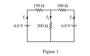
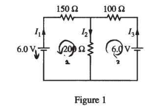
The circuit shown above is constructed with two 6.0 V batteries and three resistors with the values shown. The currents I1 , I2 , and I3 in each branch of the circuit are indicated.
(a)
i. Using Kirchhoff’s rules, write, but DO NOT SOLVE, equations that can be used to solve for the current in each resistor.
ii. Calculate the current in the 200 Ω resistor.
iii. Calculate the power dissipated by the 200 Ω resistor.
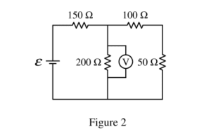
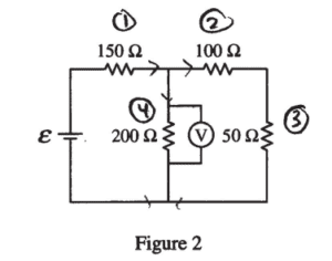
The two 6.0 V batteries are replaced with a battery with voltage ε and a resistor of resistance 50 Ω, as shown above. The voltmeter V shows that the voltage across the 200 Ω resistor is 4.4 V.
(b) Calculate the current through the 50 Ω resistor.
(c) Calculate the voltage e of the battery.
(d)
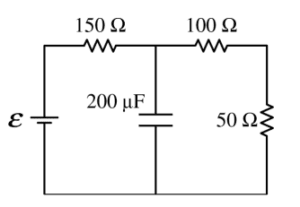
i. The 200 Ω resistor in the circuit in Figure 2 is replaced with a 200 Fμ capacitor, as shown on the right, and the circuit is allowed to reach steady state. Calculate the current through the 50 Ω resistor.
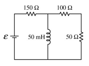
ii. The 200 W resistor in the circuit in Figure 2 is replaced with an ideal 50 mH inductor, as shown on the right, and the circuit is allowed to reach steady state. Is the current in the 50 W resistor greater than, less than, or equal to the current calculated in part (b) ?
____ Greater than ____ Less than ____ Equal to
Justify your answer.
Answer/Explanation
Ans:
(a) i.
Loop 1: 6 – 150 I1 – 200 I2 = 0
Loop 2: 6 – 100 I3 – 200 I2 = 0
I1 + I3 = I2
ii.
I1 = I2 – I3
– 6 – 150 I2 + 150 I3 – 200 I2 = 0
6 – 150 I3 – 200 I2 = 0
——————————————
-150I2 + 250 I3 = 0
I3 = 0.6 I2
6 – 100 (0.6I2 ) – 200 I2 = 0
I2 = 0.023 (A)
iii.
P = I2R = (0.023)2 (200) = 0.107 (w)
(b)
R25 = 100 + 50 = 150 Ω
V23 = V4 = 4.4 (V)
\(I_{2}=I_{3}=\frac{V_{23}}{R_{23}}=\frac{4.4}{150}=0.029 (A)\)
(c)
\(I_{1}=I_{2}+I_{4}=I_{2}+\frac{V_{4}}{R_{4}}=0.029+\frac{4.4}{200}\)
= 0.051 (A)
\(I_{1}=I_{1}R_{1}=0.051(150)=7.7(V)\rightarrow \varepsilon =V_{1}+V_{4}=7.7 + 4.4 = 12.1 (V)\)
(d)
i. E = 12.1 (V) Capacitor is a broken circuit 7)
∑R = 150 + 100 + 50 = 300 (Ω)
\(I_{1}=I_{2}=I_{3}=\frac{12.1}{300}= 0.04 (A)\)
ii. __√__ Greater than
Because the inductor is a short circuit at steady state, the loop is series – parallel, thus, the total resistance decreases, current increases
Question
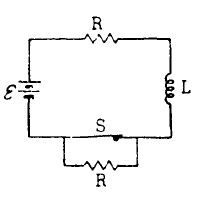
When the switch S in the circuit shown above is closed, an inductance L is in series with a
resistance R and battery of emf ε.
a. Determine the current i in the circuit after the switch S has been closed for a very long time.
After being closed for a very long time, the switch S is opened at time t = 0.
b. Determine the current iB in the circuit after the switch has been open for a very long time.
c. On the axes below, sketch a graph of the current as a function of time t for t > 0 and indicate the values
of the currents iA and iB on the vertical axis
d. By relating potential difference and emfs around the circuit, write the differential equation that can be
used to determine the current as a function of time.
e. Write the equation for the current as a function of time for all time t > 0.
Answer/Explanation
Ans.
a. After the switch has been closed for a long time, the current will have ceased changing, so the inductor voltage
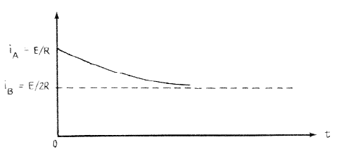
VL = L(dI/dt) = 0. Therefore the inductor can be ignored in this part of the problem and i = ε/R
b. After the switch has been opened, there are two resistors in series and iB = ε/2R
c.
d. ε = VR + VL and VR = 2Ri and VL = L(di/dt)
ε = 2Ri + L(di/dt)
e. The expression involves the exponential form e–t/τ where τ = L/2R and must satisfy the boundary conditions
i(0) = ε/R and i(∞) = ε/2R, by reasoning i(t) = (ε/2R)(1 + e–2Rt/L)