Focus Question: How can the magnetic field due to a current-carrying wire?
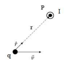
- Magnetic Field Formula – B is perpendicular to the plane containing $\vec{v}$ and $\vec{r}$ (the vector joining the source point to the field point):
$
\vec{B}=\frac{\mu_0}{4 \pi} \frac{q \vec{v} x \hat{r}}{r^2}
$
$\mu_0=$ magnetic permittivity of free space
$\mu_0=4 \pi \times 10^{-7} \mathrm{Tm} / \mathrm{A}$
$\hat{r}=\frac{\vec{r}}{|r|}$ unit vector in the direction of $\mathrm{r}$.
*B is parallel to $\vec{v} x \hat{r}$
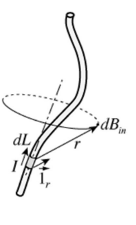
- The Biot-Savart Law is method used to find the magnetic field due some amount of length of a current- carrying wire.
- The magnetic field produced at any field point by the current in a conductor is the vector sum of the fields due to all the moving charges in the conductor. The Biot-Savart Law uses this principle with many tiny elements of length dL:
Volume of the segment: AdL
Charge in segment: $d q=($ volume $)\left(\frac{\# \text { of charg }}{\text { volume }}\right)(q)=A n q D L$
$
\begin{gathered}
d B=\frac{\mu_0 d Q v \sin \theta}{4 \pi r^2} \\
(I=A n v q) \\
d B=\frac{\mu_0 I d l \sin \theta}{4 \pi r^2}
\end{gathered}
$
The Biot-Savart Law:
$
\begin{aligned}
& \overrightarrow{\boldsymbol{d B}}=\frac{\mu_0 I}{4 \pi r^2}(\overrightarrow{d \boldsymbol{l}} x \hat{\boldsymbol{r}}) \\
& \overrightarrow{d B}=\frac{\mu_0 I}{4 \pi r^3}(\overrightarrow{d l} x \vec{r}) \\
&
\end{aligned}
$
*The magnetic field produced by current in a conductor is the vector sum of all moving charges in the conductor.
$* \mathrm{~d} \vec{l}$ is a vector in the same direction as the current in the conductor.
$* \vec{r}$ is the vector from the wire to the point where field is being calculated.
*Field lines produced by the current element are circles in planes perpendicular to dl. The direction of the field is given by the right-hand rule.
Example A: Derive the magnetic field due to the current carrying loop at the center of the loop.
Answer/Explanation
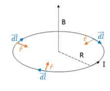
The current carrying-loop is broken up in many tiny current elements, $\overrightarrow{d l}$. Every $\overrightarrow{d l}$ is perpendicular to its corresponding $\vec{r}$ vector, so $\overrightarrow{d l} x \hat{r}$ is simply equal to $|d l \| \hat{r}| \sin 90^{\circ}=d l$. This is true whenever the two vectors are perpendicular.
$
d B=\frac{\mu_0 I}{4 \pi R^2}(\overrightarrow{d l} x \hat{r}) \rightarrow B=\int \frac{\mu_0 I}{4 \pi R^2}(\overrightarrow{d l} x \hat{r}) \rightarrow B=\frac{\mu_0 I}{4 \pi R^2} \int d l
$
The integral of $\int d l$ is simply the circumference of the circle.
$
B=\frac{\mu_0 I}{4 \pi R^z}(2 \pi R) \rightarrow \boldsymbol{B}=\frac{\boldsymbol{\mu}_{\mathbf{0}} \boldsymbol{I}}{2 \boldsymbol{R}}
$
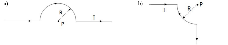
Example B: Use the Biot-Savart law to calculate the magnetic field at point P in the two cases below.
Answer/Explanation
a) For the first straight segment, the angle between $\overrightarrow{d l}$ and $\hat{r}$ is $0^{\circ}$, so $\overrightarrow{d l} x \hat{r}|d l||\hat{r}| \sin 0^{\circ}=0$, so there is no field. For the curved segment, the angle between $\overrightarrow{d l}$ and $\hat{r}$ is always $90^{\circ}, \overrightarrow{d l} x \hat{r}|d l||\hat{r}| \sin 90^{\circ}=d l$, so $\int \overrightarrow{d l} x \hat{r}$ will simply be each to the distance through the semi-circle.
For the segment straight segment, the angle between $\overrightarrow{d l}$ and $\hat{r}$ is $0^{\circ}$, so $\overrightarrow{d l} x \hat{r}|d l||\hat{r}| \sin 180^{\circ}=0$
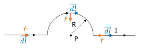
Only the curved portion contributes to the electric field, so the Biot-Savart Law will be applied for this segment only:
$\begin{aligned} & d B=\frac{\mu_0 I}{4 \pi R^2}(\overrightarrow{d l} x \hat{r}) \rightarrow B=\int \frac{\mu_0 I}{4 \pi R^2}(\overrightarrow{d l} x \hat{r}) \rightarrow B=\frac{\mu_0 I}{4 \pi R^2} \int d l=\frac{\mu_0 I}{4 \pi R^2}(\pi R) \\ & \rightarrow \boldsymbol{B}=\frac{\boldsymbol{\mu}_0 I}{4 \boldsymbol{4 R}}\end{aligned}$
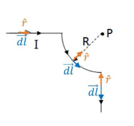
(b) Just as in part a), the field is zero in the straight segment, so the Biot-Savart Law is applied only for the quarter circle segment:
$
\begin{aligned}
& d B=\frac{\mu_0 I}{4 \pi R^2}(\overrightarrow{d l} x \hat{r}) \rightarrow B=\int \frac{\mu_0 I}{4 \pi R^2}(\overrightarrow{d l} x \hat{r}) \rightarrow B=\frac{\mu_0 I}{4 \pi R^2} \int d l=\frac{\mu_0 I}{4 \pi R^2}\left(\frac{\pi R}{2}\right) \\
& \rightarrow \boldsymbol{B}=\frac{\boldsymbol{\mu}_0 \boldsymbol{I}}{\mathbf{8 R}}
\end{aligned}
$
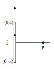
Example C: Consider a wire carrying a current I that extends along the y-axis from (0,-a) to (0,a) . Find the magnetic field at point P, x away from the center of the wire along the x- axis.
Answer/Explanation
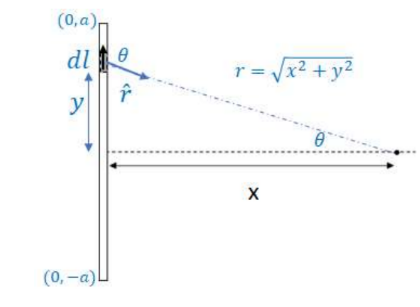
Each current-carrying element is along the y-axis, so $d l=d y$ and $(\overrightarrow{d l} x \hat{r})=d y \sin \theta$, where $\theta$ is the angle between $\overrightarrow{d l}$ and $\hat{r}$.
$\begin{gathered}d B=\frac{\mu_0 I}{4 \pi R^2}(\overrightarrow{d l} x \hat{r}) \\ B=\int_{-a}^a \frac{\mu_0 I d y \sin \theta}{4 \pi r^2}=2 \int_0^a \frac{\mu_0 I d y \sin \theta}{4 \pi r^2}\end{gathered}$
${ }^* r=\sqrt{x^2+y^2}$ and $\sin \theta=\frac{x}{\sqrt{x^2+y^2}}$
$
B=2 \int_0^a \frac{\mu I d y}{4 \pi\left(x^2+y^2\right)} \frac{x}{\sqrt{x^2+y^2}} \rightarrow B=\frac{2 \mu_0 I x}{4 \pi} \int_0^a \frac{d y}{\left(x^2+y^2\right)^{\frac{3}{2}}}
$
$\rightarrow B=\left.\frac{\mu I x}{2 \pi}\left(\frac{y}{x^2 \sqrt{x^2+y^2}}\right)\right|_0 ^a \rightarrow \boldsymbol{B}=\frac{\boldsymbol{\mu}_0 \boldsymbol{I}}{2 \pi x} \frac{\boldsymbol{a}}{\sqrt{\boldsymbol{a}^2+x^2}}$
- B for an infinitely long conductor can be found by taking the limit as $a \rightarrow \infty$ $B=\lim _{a \rightarrow \infty} \frac{\mu_0 I}{2 \pi x} \frac{a}{\sqrt{a^2+x^2}} \quad \rightarrow \boldsymbol{B}=\frac{\mu_0 I}{2 \pi x}$ where $\mathrm{x}$ is the distance to the wire
Example D: Find the magnetic field in the center of the rectangular loop.
Answer/Explanation
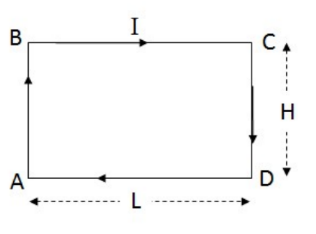
The rectangle consists of 4 wires of finite length, with two pairs of wires with identical fields. This problem can be simplified with using the result for a wire of finite length from C.
$B=2\left(\frac{\mu_0 I}{2 \pi \frac{L}{2}} \frac{\frac{H}{2}}{\sqrt{\left(\frac{H}{2}\right)^2+\left(\frac{L}{2}\right)^2}}\right)+2\left(\frac{\mu_0 I}{2 \pi \frac{H}{2}} \frac{\frac{L}{2}}{\sqrt{\left(\frac{H}{2}\right)^2+\left(\frac{L}{2}\right)^2}}\right) \rightarrow B=\frac{2 \mu_0 I}{\pi L H}$
The field is into the page using the right hand rule with any of the segments of wire.
Focus Question: What is Ampere’s Law used for?
- Ampere’s Law plays the same role for magnetic fields that Gauss’s Law plays for electric fields: $>$ Gauss’s Law for electric fields relates the integral of the perpendicular component of the electrical field over a closed surface to the total charge enclosed by the surface.
- Ampere’s Law for magnetic fields relates the integral of the tangential component of a magnetic field at points on a closed curve to the current passing through the area bounded by the curve.
- Consider a long straight wire carrying current I. Choose a circle perpendicular to the wire and center on the wire as the path:
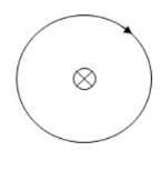
$\oint B \cdot d l$ is a line integral, which is evaluated by dividing the path in a bunch of $d l$ ‘s. The line integral adds up $B \cdot d l$ for all the dl’s along the length.
Everywhere on the path, the magnitude of B is constant and tangent to the circle. B is equal to $\frac{\mu_o I}{2 \pi r}$ at all points, where is the distance to the wire.
$
\begin{aligned}
& \oint B \cdot d l=B \oint d l=\frac{\mu_0 I}{2 \pi r} \oint d l=\frac{\mu_0 I}{2 \pi r}(2 \pi r) \\
& \rightarrow B=\mu_0 I
\end{aligned}
$
- Ampere’s Law: Ampere’s Law is used to find the magnetic field at some distance from a currentcarrying wire:
$
\oint B \cdot d l=\mu_0 I_{e n c}
$
*Chose an integration path that is a closed loop that passes through the point where you want to calculate the magnetic field. If the integration path is a circle, then $\oint d l=2 \pi r$.
Gauss’s Law used an imaginary surface that enclosed the charge the electric field due to that charge. Ampere’s Law involves drawing an imaginary loop, or path, around the current that the magnetic field is being calculated for. As with Gauss’s law, the Amperian path chosen needs to have appropriate symmetry.
Example A: Field around a long straight conductor.
Answer/Explanation
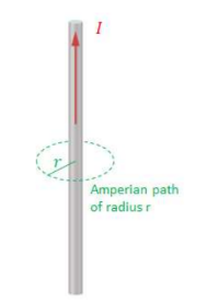
An Amperian circle or radius is drawn around the conducting wire. The circle encloses all the current of the wire:
$\begin{aligned} & \oint B \cdot d l=\mu_0 I_{\text {enc }} \\ & \rightarrow B \oint d l=\mu_0 I \rightarrow B(2 \pi r)=\mu_0 I \\ & \rightarrow \boldsymbol{B}=\frac{\boldsymbol{\mu}_0 \boldsymbol{I}}{\mathbf{2} \boldsymbol{r}}\end{aligned}$
FB is constant and tangent to the circle at all points, so $\oint B \cdot d l$ simply equal to B times the length of the Amperian path, which is common for most cases in which Ampere’s Law is applied in Physics C.
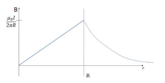
Example B: Field inside a long straight conductor.
Answer/Explanation
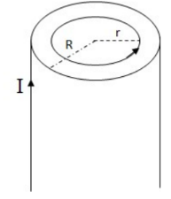
The Amperian path is again a circle. Since the field is to be found inside the conductor, the path is chosen with $\mathrm{r}<\mathrm{R}$. The path only encloses part of the current, so the current enclosed will be: $I_{e n c}=$ current density $*$ area enclosed $\rightarrow I_{\text {enc }}=J A$
$
\begin{aligned}
& \oint B \cdot d l=\mu_0 I_{\text {enc }} \rightarrow B(2 \pi r)=\mu_0 J A_{\text {enc }} \\
& \rightarrow B(2 \pi \boldsymbol{f})=\frac{\mu_0 I}{\tilde{H}^2}\left(\tilde{H} r^z\right) \rightarrow \boldsymbol{B}=\frac{\mu_0 \boldsymbol{I r}}{2 \pi \boldsymbol{R}^2}
\end{aligned}
$
Graph for the field due to a current-carrying as a function of distance from the center of the wire:
Example C: Field inside a solenoid.
- A solenoid is a helical winding of wire around a cylinder. The turns are closely spaced so that each can be considered as a circle. When the solenoid is long compared to its cross-sectional area, the field near the center can be considered uniform. The external field is small. Ampere’s Law for a solenoid is used to find the internal field.
Answer/Explanation
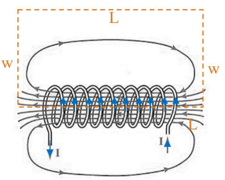
An Amperian circle would have no symmetry here, so the Amperian path is a rectangle as shown. For the long part of the rectangle running through the center of the solenoid, $\oint B \cdot d l=B \oint d l$ since $\mathrm{B}$ is parallel to the field and constant inside. For the long section outside the solenoid, the field is negligible. For the two widths of the rectangle, $\mathrm{B}$ is perpendicular to the field, so $\oint B \cdot d l=0$.
Ampere’s Law is applied only for the long segment inside the solenoid:
$
\oint B \cdot d l=\mu_0 I_{e n c}
$
The current enclosed is NI, where N is the number of loops in the solenoid. Each loop of wire carries the current, so each loop enclosed will enclose the current.
$
\begin{aligned}
& \rightarrow B \int d l=\mu_0 N I \rightarrow B L=\mu_0 N I \\
& \rightarrow \boldsymbol{B}=\frac{\mu_0 N I}{L}
\end{aligned}
$
The field for a solenoid is also written as $B=\mu_0 n I$, where $\mathrm{n}$ is the number of loops per unit length: $\mathrm{n}=\mathrm{N} / \mathrm{L}$.
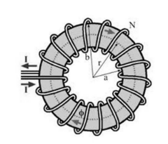
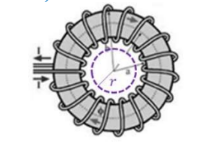
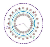
A toroid, or toroidal solenoid is formed by winding wire around a ring. It is essential a solenoid bent into a circle so both ends meet. A toroid has all of its field within the region between the wires. Since current flows in opposite directions on the inner and outer parts of the region, the total current enclosed outside of the toroid is zero.
Example D: Field inside a toroid.
Find the field in the following regions:
a) $\mathrm{r}<\mathrm{a}$
b) $r>b$
c) a $<$ r $<$ b
Answer/Explanation
For all parts, the Amperian path will be a circle in order to have the appropriate symmetry with the circular toroid.
a) The current enclosed by the path is zero.
$\begin{aligned} & \oint_{\rightarrow B} B \cdot d l=\mu_0 I_{\text {enc }} \rightarrow I_{\text {enc }}=0 \\ & \rightarrow 0\end{aligned}$
b) As with the solenoid, the toroid encloses the current on the inner part N times, where N is the number of loops.
$\begin{aligned} & \oint_{\rightarrow} B d l=\mu_0 I_{\text {enc }} \rightarrow B \oint d l=\mu_0 N I \\ & \rightarrow B(2 \pi r)=\mu_0 N I \\ & \rightarrow B=\frac{\mu_0 N I}{2 \pi r}\end{aligned}$
c) As shown on the diagram, the current flows into the page on the inner part of the toroid, and out of the page on the outer surface, so every loop contains current flowing into and out of the page, making the total current enclosed by the Amperian loop zero.
$\begin{aligned} & \oint_{\rightarrow B} \cdot d l=\mu_0 I_{e n c} \rightarrow I_{\text {enc }}=0 \\ & \rightarrow B=0\end{aligned}$
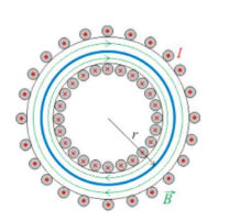
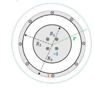
Example E: Coaxial Cable
- A coaxial conductor consists of a cylindrical conductor or radius R1 that carries current I into the page and an outer cylindrical conductor (of inner radius R2 and outer radius R3) that carries current I out of the page.
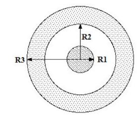
Find the field for:
Answer/Explanation
a) R $_1<$ r $<\mathrm{R}_2$
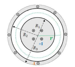
Only the current on the inner conductor is enclosed:
$
\begin{aligned}
& \oint B \cdot d l=\mu_0 I_{\text {enc }} \\
& \rightarrow B \oint d l=\mu_0 I \rightarrow B(2 \pi r)=\mu_0 I \\
& \rightarrow \boldsymbol{B}=\frac{\boldsymbol{\mu}_0 \boldsymbol{I}}{2 \pi r}
\end{aligned}
$
b) $\mathrm{R}>\mathrm{R}_3$
The currents flow in opposite direction.
$
\begin{aligned}
& \oint B \cdot d l=\mu_0 I_{e n c} \\
& \rightarrow B \oint d l=\mu_0(I-I) \\
& \rightarrow \boldsymbol{B}=\mathbf{0}
\end{aligned}
$