Question 1
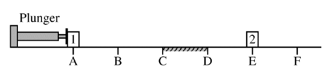
Identical blocks \( 1 \) and \( 2 \) are placed on a horizontal surface at points \( A \) and \( E \), respectively, as shown. The surface is frictionless except for the region between points \( C \) and \( D \), where the surface is rough. Beginning at time \( t_A \), block \( 1 \) is pushed with a constant horizontal force from point \( A \) to point \( B \) by a mechanical plunger. Upon reaching point \( B \), block \( 1 \) loses contact with the plunger and continues moving to the right along the horizontal surface toward block \( 2 \). Block \( 1 \) collides with and sticks to block \( 2 \) at point \( E \), after which the two-block system continues moving across the surface, eventually passing point \( F \).
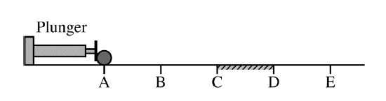
(b) The plunger is returned to its original position, and both blocks are removed. A uniform solid sphere is placed at point \( A \), as shown. The sphere is pushed by the plunger from point \( A \) to point \( B \) with a constant horizontal force that is directed toward the sphere’s center of mass. The sphere loses contact with the plunger at point \( B \) and continues moving across the horizontal surface toward point \( E \). In which interval(s), if any, does the sphere’s angular momentum about its center of mass change? Check all that apply.
Most-appropriate topic codes (AP Physics 1):
• Topic \( 4.2 \) — Change in Momentum and Impulse (Part \( \mathrm{(a)} \))
• Topic \( 4.3 \) — Conservation of Linear Momentum (Part \( \mathrm{(a)} \))
• Topic \( 6.3 \) — Angular Momentum and Angular Impulse (Part \( \mathrm{(b)} \))
• Topic \( 2.9 \) — Circular Motion (Part \( \mathrm{(b)} \), rotational change about the center of mass)
• Topic \( 1.3 \) — Representing Motion (Part \( \mathrm{(a)} \))
▶️ Answer/Explanation
(a)
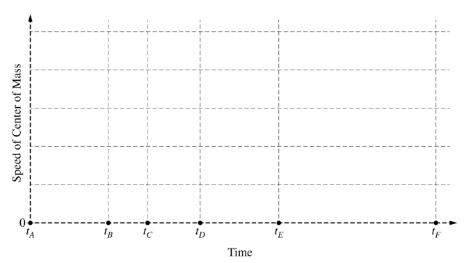
The center-of-mass speed graph should have these pieces:
\( \bullet \) From \( t_A \) to \( t_B \): a straight line starting at \( 0 \) and increasing linearly
\( \bullet \) From \( t_B \) to \( t_C \): a horizontal, nonzero segment
\( \bullet \) From \( t_C \) to \( t_D \): a straight line decreasing linearly
\( \bullet \) From \( t_D \) to \( t_F \): a horizontal, nonzero segment at a lower value than the segment from \( t_B \) to \( t_C \)
A correct sketch is shown below.
Explanation:
From \( A \) to \( B \), the plunger applies a constant external force to the two-block system, so the center of mass has a constant acceleration and its speed increases linearly.
From \( B \) to \( C \), there is no external horizontal force, so the center-of-mass speed remains constant.
From \( C \) to \( D \), friction acts externally on the system, so the center-of-mass speed decreases linearly.
From \( D \) to \( F \), the surface is frictionless again, so the center-of-mass speed stays constant.
There is no jump in the center-of-mass speed at \( t_E \), because the collision between the blocks is internal to the two-block system. Internal forces can change the motion of individual blocks, but not the motion of the center of mass of the whole system.
(b)
\( \boxed{C \text{ to } D} \)
The sphere’s angular momentum about its center of mass changes only during the interval from \( C \) to \( D \).
From \( A \) to \( B \), the plunger force is directed through the sphere’s center of mass, so it exerts no torque about the center of mass. Therefore, it does not change the sphere’s angular momentum about its center of mass.
From \( B \) to \( C \) and from \( D \) to \( E \), the surface is frictionless, so there is no external torque about the center of mass that would change the sphere’s rotation.
In the rough interval from \( C \) to \( D \), friction acts at the contact point with the surface. That friction force produces an external torque about the center of mass, so the sphere’s angular momentum changes there.
Question 2
Most-appropriate topic codes (AP Physics 1):
• Topic \( 2.5 \) — Newton’s Second Law (Part \( \mathrm{(a)} \), Part \( \mathrm{(c)} \), Part \( \mathrm{(d)} \), Part \( \mathrm{(e)} \))
• Topic \( 2.6 \) — Gravitational Force (Part \( \mathrm{(a)} \), Part \( \mathrm{(b)} \), Part \( \mathrm{(c)} \), Part \( \mathrm{(d)} \), Part \( \mathrm{(e)} \))
• Topic \( 5.6 \) — Newton’s Second Law in Rotational Form (Part \( \mathrm{(e)} \), through the effect of pulley inertia)
• Topic \( 3.A \) / Scientific Questioning and Argumentation (Part \( \mathrm{(d)} \))
▶️ Answer/Explanation
(a)(i)
The acceleration is approximately \( \boxed{0} \), or extremely small.
If block \( A \) is much more massive than block \( B \), then block \( A \) has a very large inertia and is hard to accelerate. The hanging block is too light to produce much motion, so the whole system accelerates only a tiny amount.
In words: the heavy block on the table is so difficult to speed up that the system barely moves.
(a)(ii)
The acceleration is approximately \( \boxed{g} \) \( \big(\text{or about } 9.8\ \mathrm{m/s^2}\big) \).
If block \( A \) is much less massive than block \( B \), then block \( A \) offers very little resistance to the motion. The hanging block behaves almost like a freely falling mass, so the acceleration approaches \( g \).
It is not exactly equal to \( g \) unless the other mass becomes negligible, but it gets very close.
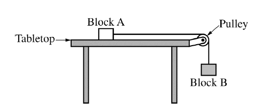
(b)
The correct free-body diagrams are:
For block \( A \):
\( \bullet \) Normal force \( F_N \) upward
\( \bullet \) Gravitational force \( F_g \) downward
\( \bullet \) Tension force \( F_T \) horizontally to the right
For block \( B \):
\( \bullet \) Tension force \( F_T \) upward
\( \bullet \) Gravitational force \( F_g \) downward
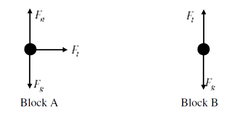
There is no friction force on block \( A \), because the tabletop is stated to have negligible friction.
(c)
Apply Newton’s second law separately to each block.
For block \( A \) \( (\text{horizontal direction}) \):
\( F_T = m_A a \)
For block \( B \) \( (\text{taking downward as positive}) \):
\( m_B g – F_T = m_B a \)
Substitute \( F_T = m_A a \) into the equation for block \( B \):
\( m_B g – m_A a = m_B a \)
\( m_B g = m_A a + m_B a \)
\( m_B g = (m_A + m_B)a \)
Solve for \( a \):
\( \boxed{a = \dfrac{m_B}{m_A + m_B}\,g} \)
This expression makes good physical sense: increasing \( m_B \) makes the pull stronger, while increasing either mass increases the inertia of the moving system.
(d)
\( \boxed{\text{Yes}} \)
The equation from part \( \mathrm{(c)} \) is \( a = \dfrac{m_B}{m_A + m_B}g \). When \( m_A \ll m_B \), the term \( m_A \) is negligible compared with \( m_B \), so
\( a \approx \dfrac{m_B}{m_B}g = g \)
Therefore the equation predicts that the acceleration approaches \( g \), which matches the reasoning in part \( \mathrm{(a)(ii)} \).
(e)
\( \boxed{T_2 > T_1} \)
When the pulley has nonnegligible mass, some of the net force effect goes into rotating the pulley as well as accelerating the blocks. That makes the acceleration of the blocks smaller than before.
For block \( B \), the forces are weight downward and tension upward. If the downward acceleration becomes smaller while \( m_B g \) stays the same, then the upward tension must be larger. So the tension in the vertical part of the string is greater with the massive pulley.
In other words, a rotationally inert pulley reduces the system’s acceleration, which means the hanging block’s net downward force is smaller, so the tension has to be closer to the block’s weight.
Question 3
| Quantity to be Measured | Symbol for Quantity | Equipment for Measurement |
|---|---|---|
Most-appropriate topic codes (AP Physics 1):
• Topic \( 3.4 \) — Conservation of Energy (Part \( \mathrm{(a)} \), Part \( \mathrm{(b)} \), Part \( \mathrm{(c)} \), Part \( \mathrm{(d)} \))
• Topic \( 3.1 \) — Translational Kinetic Energy (Part \( \mathrm{(a)} \), Part \( \mathrm{(b)} \), Part \( \mathrm{(c)} \), Part \( \mathrm{(d)} \))
• Topic \( 1.3 \) — Representing Motion (Part \( \mathrm{(d)} \))
• Topic \( 3.A \) — Scientific Questioning and Argumentation (Part \( \mathrm{(b)} \), Part \( \mathrm{(c)} \))
▶️ Answer/Explanation
(a)(i)
A valid principle is conservation of energy.
The elastic potential energy stored in the compressed spring is converted into the kinetic energy of the sphere at launch, neglecting friction and other losses.
(a)(ii)
If the spring is compressed a distance \( \Delta x \), then using conservation of energy:
\( \dfrac{1}{2}k(\Delta x)^2 = \dfrac{1}{2}mv^2 \)
Solving for \( k \),
\( \boxed{k = \dfrac{mv^2}{(\Delta x)^2}} \)
Here, \( m \) is the sphere’s mass, \( v \) is its launch speed, and \( \Delta x \) is the compression distance. These can all be measured with standard lab equipment.
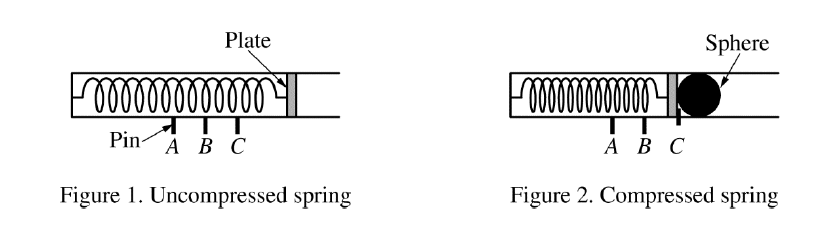
(b)
One valid experimental design is to launch the sphere horizontally and measure its launch speed with a motion sensor.
| Quantity to Be Measured | Symbol for Quantity | Equipment for Measurement |
|---|---|---|
| Mass of sphere | \( m \) | Triple-beam balance |
| Spring compression distance | \( \Delta x \) | Ruler or meterstick |
| Launch speed of sphere | \( v \) | Motion sensor |
Procedure:
Measure the mass \( m \) of the sphere with a triple-beam balance. Set the launcher on a level surface aimed horizontally toward a motion sensor. Compress the spring to pin position \( A \), and measure the corresponding compression distance \( \Delta x_A \) with a ruler, relative to the spring’s unstretched position.
Release the pin and record the launch speed \( v_A \) of the sphere from the motion sensor. Repeat the launch at least three times for pin position \( A \), and average the speeds to reduce random error.
Repeat the same process for pin positions \( B \) and \( C \), measuring \( \Delta x_B \), \( \Delta x_C \), and the corresponding average launch speeds \( v_B \) and \( v_C \).
Keep the launcher angle the same for all trials and use the same sphere each time. Repeating trials and averaging improves reliability, and measuring each compression directly avoids assuming equally spaced pin positions.
Another acceptable method would be to launch the sphere horizontally and determine \( v \) from range and fall time, or to launch vertically and determine \( v \) from maximum height.
(c)
For each pin position, calculate the spring constant using
\( k = \dfrac{mv^2}{(\Delta x)^2} \)
so that you obtain values \( k_A \), \( k_B \), and \( k_C \).
Then compare the three calculated values. If the values of \( k \) agree within experimental uncertainty, the hypothesis is supported. If the values differ by more than the uncertainty, the hypothesis is not supported.
A nice check is to compare percent differences between the calculated \( k \)-values and see whether those differences are comparable to the experimental uncertainty from the speed and compression measurements.
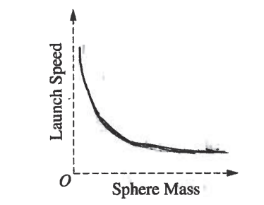
(d)
Since each sphere is launched from the same pin position \( A \), the spring compression is the same each time, so the stored spring energy is the same:
\( \dfrac{1}{2}k(\Delta x)^2 = \dfrac{1}{2}mv^2 \)
Thus,
\( v = \sqrt{\dfrac{k(\Delta x)^2}{m}} \)
so launch speed decreases as sphere mass increases. Because \( v \propto \dfrac{1}{\sqrt{m}} \), the graph is a decreasing curve that is concave up.
A correct sketch is shown below.
Question 4
Most-appropriate topic codes (AP Physics 2):
• Topic \( 11.5 \) — Compound Direct Current (DC) Circuits (Part \( \mathrm{(b)} \))
• Topic \( 11.6 \) — Kirchhoff’s Loop Rule (Part \( \mathrm{(b)} \))
• Skill \( 3.B \) — Apply an appropriate law, definition, theoretical relationship, or model to make a claim (Part \( \mathrm{(b)} \))
• Skill \( 3.C \) — Justify or support a claim using evidence from experimental data, physical representations, or physical principles or laws (Part \( \mathrm{(b)} \))
▶️ Answer/Explanation
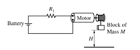
(a)
The block is lifted at constant speed, so the motor’s mechanical work goes into increasing the block’s gravitational potential energy.
The work done on the block is
\( W = MgH \)
Mechanical power is work done per unit time, so
\( P = \dfrac{W}{\Delta t} \)
Therefore,
\( \boxed{P = \dfrac{MgH}{\Delta t}} \)
Since \( M \) and \( H \) are fixed, decreasing \( \Delta t \) means the motor must deliver a larger power.
(b)
\( \boxed{\text{In parallel with } R_1} \)
To decrease \( \Delta t \), the motor must lift the same block through the same height in less time. From part \( \mathrm{(a)} \), that means the required mechanical power must increase:
\( P = \dfrac{MgH}{\Delta t} \)
The problem states that the mechanical power of the motor increases when the potential difference across the motor increases. Therefore, to reduce \( \Delta t \), we must increase the voltage across the motor.
The motor and \( R_1 \) are originally in series, so the battery voltage is shared between them. If a resistor \( R_2 \) is added in parallel with \( R_1 \), the equivalent resistance of that branch becomes smaller than \( R_1 \) alone:
\( R_{\text{eq}} = \dfrac{R_1 R_2}{R_1 + R_2} \)
so \( R_{\text{eq}} < R_1 \).
This reduces the resistance of the non-motor part of the series circuit, which increases the total current. Because the motor is still in series with the rest of the circuit, the current through the motor also increases. Since the motor has constant resistance, its voltage drop is
\( \Delta V_{\text{motor}} = I R_{\text{motor}} \)
so a larger current means a larger potential difference across the motor.
A larger voltage across the motor means a larger mechanical power output, so the motor lifts the block faster. Therefore, the time interval \( \Delta t \) decreases.
The other options do not help in the same way: putting \( R_2 \) in series would increase total resistance and reduce current, while putting it in parallel with the motor would not be the correct way to increase the motor’s power in this setup.
Question 5
Most-appropriate topic codes (AP Physics 2):
• Topic \( 14.5 \) — The Doppler Effect / Sound-Wave Descriptions Context (Part \( \mathrm{(a)} \), Part \( \mathrm{(b)} \), Part \( \mathrm{(c)} \), through sound behavior in air columns)
• Topic \( 1.B \) — Create quantitative graphs with appropriate scales and units, including plotting data (Part \( \mathrm{(b)} \))
• Topic \( 1.C \) — Create qualitative sketches of graphs that represent features of a model or the behavior of a physical system (Part \( \mathrm{(b)} \))
• Topic \( 2.B \) — Calculate or estimate an unknown quantity from known quantities (Part \( \mathrm{(a)} \), Part \( \mathrm{(c)} \))
▶️ Answer/Explanation
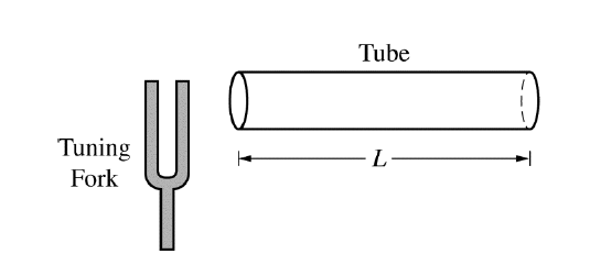
(a)
For a tube open at both ends at the fundamental frequency,
\( L = \dfrac{\lambda}{2} \)
First find the wavelength:
\( \lambda = \dfrac{v}{f} = \dfrac{340\ \mathrm{m/s}}{512\ \mathrm{Hz}} \approx 0.664\ \mathrm{m} \)
Therefore,
\( L = \dfrac{0.664}{2} \approx 0.332\ \mathrm{m} \)
\( \boxed{L \approx 0.33\ \mathrm{m}} \)
This fits the open-open fundamental pattern, which has antinodes at both ends and one half-wavelength inside the tube.
(b)
The maximum particle speed has antinodes at both open ends and a node at the middle of the tube. So the graph:
\( \bullet \) is maximum at \( x=0 \)
\( \bullet \) decreases to \( 0 \) at \( x=\dfrac{L}{2} \)
\( \bullet \) increases back to a maximum at \( x=L \)
\( \bullet \) is symmetric about \( x=\dfrac{L}{2} \)
A correct sketch is: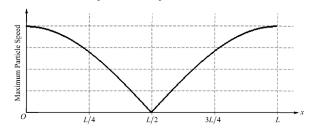
Physically, open ends of an air column correspond to displacement antinodes, so particle motion is greatest there.
(c)
Now the tube is open at one end and closed at the other, so the fundamental mode satisfies
\( L = \dfrac{\lambda}{4} \)
Thus,
\( f = \dfrac{v}{4L} \)
Using \( v = 1005\ \mathrm{m/s} \) and \( L \approx 0.332\ \mathrm{m} \),
\( f = \dfrac{1005}{4(0.332)} \approx 757\ \mathrm{Hz} \)
So the new fundamental frequency is
\( \boxed{7.6 \times 10^2\ \mathrm{Hz}} \)
or about \( \boxed{757\ \mathrm{Hz}} \).
The frequency increases because the sound speed is larger, but it is also affected by the boundary condition changing from open-open to open-closed.