Question 1
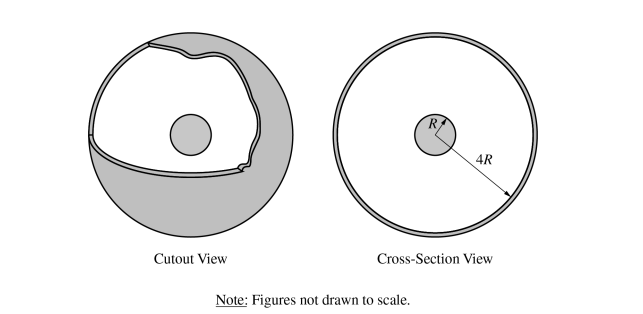
1. A nonconducting sphere of uniform volume charge density is surrounded by a thin concentric conducting spherical shell, as shown in the cutout view. The sphere has a charge of −Q and the shell has a charge of +3Q. The radii of the inner sphere and spherical shell are R and 4R, respectively, as shown in the cross-section view.
(a) Determine the charge on the outer surface of the shell.
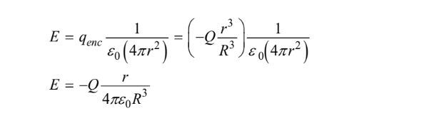
(b) Using Gauss’s law, derive an expression for the electric field a distance r from the center of the sphere for r < R. Express your answer in terms of Q, R, r, and physical constants, as appropriate.
(c) The magnitude of the electric field at r = R is 8N / C. Calculate the value of the electric field at r = 2R.
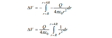
(d) Derive an expression for the absolute value of the potential difference between the outer surface of the sphere and the inner surface of the shell. Express your answer in terms of Q, R, and physical constants, as appropriate.
(e)
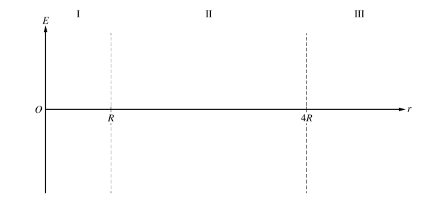
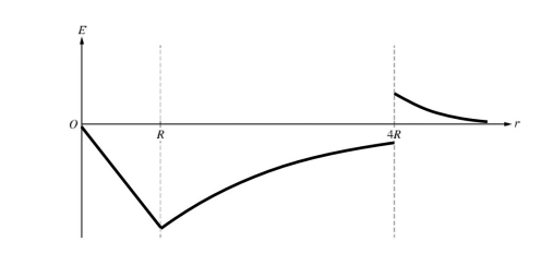
i. On the following axes that include regions I, II, and III, sketch a graph of the electric field E as a function of the distance r from the center of the sphere.
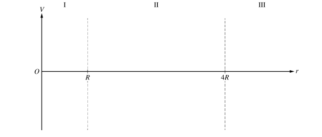
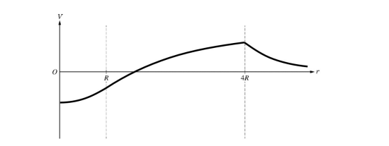
ii. On the following axes that include regions I, II, and III, sketch a graph of the electric potential V as a function of the distance r from the center of the sphere.
▶️Answer/Explanation
1(a) Example Response
\(q_{net} = q_{inner} + q_{outer}\)
\(q_{outer} = q_{net} – q_{inner}\)
\(q_{outer} = +3Q – (+Q)\)
\(q_{outer} = +2Q \)
1(b) Example Response
1(c) Example Response
\(E_{new} = \frac{E_{old}}{4} = \frac{8 N/C}{4}\)
\(E_{new} = 2 N/C\)
(d) Example Response
1(e) (i) Example Response
1(e) (ii) Example Response
Question 2
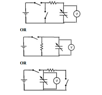
2. The plates of a certain variable capacitor have an adjustable area. An experiment is performed to study the potential difference across the capacitor as it discharges through a resistor. A circuit is to be constructed with the following available equipment: a single ideal battery of potential difference \(\Delta V_{o}\) , a single voltmeter, a single resistor of resistance R, a single uncharged variable capacitor set to capacitance C, and one or more switches as needed
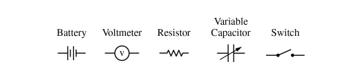
(a) Using the symbols shown, draw a schematic diagram of a circuit that can charge the capacitor and may also be The capacitor is fully charged by the battery. At time t = 0, the capacitor starts discharging through the resistor.
The capacitor is fully charged by the battery. At time t = 0, the capacitor starts discharging through the resistor.
(b) Show that the potential difference \(\Delta V_{C}\) across the capacitor as a function of time t is \( \Delta V_{c}(t)= \Delta V_{0}e^{-\frac{t}{RC}}\) as the capacitor discharges.
(c) The experiment is performed using a resistor of R = 150 kΩ. Data for the potential difference \(\Delta V_{C}\) across the capacitor as a function of t are recorded and a plot of In \(\frac{\Delta V_{C}}{\Delta V_{O}}\) as a function of t is created on the graph below.
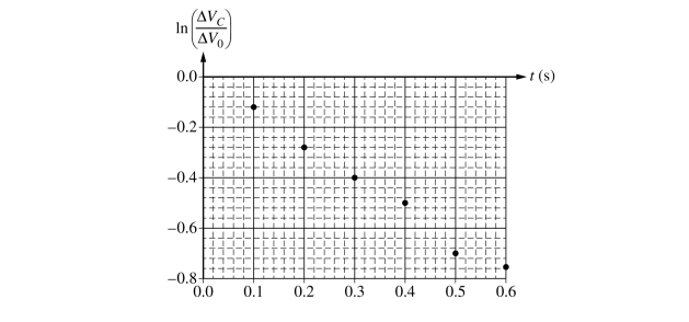
i. Draw the best-fit line for the data.
ii. Using the best-fit line, calculate a value for the unknown capacitance C.
(d) The capacitor is adjusted so that the surface area of the plates is increased, and the experiment is repeated. Would the slope of the best-fit line in the second experiment be more steep, less steep, or unchanged compared to the slope of the best-fit line in part (c)?
___ More steep ___ Less steep ___ Unchanged
Briefly justify your answer.
(e) The ideal battery is then replaced with a non-ideal battery with internal resistance r, and the experiment is repeated.
i. Would the slope of the graph in this final experiment change compared to the graph in part (c)?
___ Yes ___ No
Briefly justify your answer.
ii. Would the vertical intercept of the graph in this final experiment change compared to the graph in part (c)?
___ Yes ___ No
Briefly justify your answer
▶️Answer/Explanation
2(a) Example Responses
2(b) Example Responses
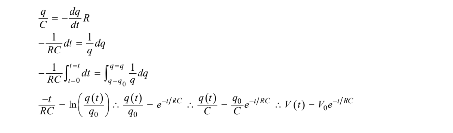
Scoring Note: The point can be earned regardless of the sign used in the substitution of \(\frac{dq}{dt}\) for the current.
2(c) (i) Example Responses
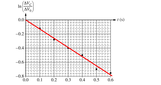
2(c) (ii) Example Responses
\(slope = -\frac{1}{RC} \therefore C = \frac{-1}{slope * (R)} =\frac{-1}{(-1.25\\\ s^{-1}) * (150\\\\ k\Omega )} = 5\\\ \mu F\)
2(d) Example Responses
Increasing the area of the plates increases the capacitance of the capacitor; thus, the magnitude of the slope will decrease.
Scoring Note: Part (d) is scored consistently with part (c).
2(e) (i) Example Responses
No. The capacitor still discharges only though resistor R , so the slope is the same
2(e) (ii) Example Responses
No. The best-fit line does not change, because the internal resistance of the battery does not affect the final potential difference across the charging capacitor.
Scoring Note: This point is scored with consistency with the circuit drawn in part (b).
Question 3
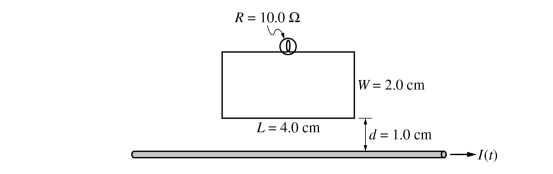
3. A lightbulb of resistance R = 10.0 Ω is connected to a rectangular loop of wire of negligible resistance near a very long current-carrying wire. The rectangular loop has a length L = 4.0 cm and a width W = 2.0 cm and is positioned so one of the longer sides of the loop is a distance d = 1.0 cm above and parallel to the long wire, as shown. The current in the long wire is initially flowing to the right and is given by I(t ) = C − Dt, where C = 10.0 A and D = 2.0 A/s. At time t = 5.0 s, the current in the long wire is instantaneously zero as the current changes direction.
(a) What is the direction, if any, of the magnetic field produced by the induced current in the rectangular loop as the current in the long wire changes direction?
___ Into the page ___ Out of the page ___ No direction, because the field is zero
Justify your answer.
b) Calculate the magnetic flux through the loop due to only the long wire at time t = 3.0 s.
(c) Calculate the current through the lightbulb at time t = 3.0 s.
(d) A group of students attempts to experimentally verify whether the current through the lightbulb is consistent with the current calculation from part (c). The current in the rectangular loop is measured to be greater than the current calculated in part (c). Which of the following could explain this discrepancy? Select one answer.
___ The students did not account for Earth’s magnetic field.
___ The rectangular loop is tilted and is not in the same plane as the wire.
___ The resistance of the lightbulb is greater than the recorded value.
___ The long side of the rectangular loop is shorter than the recorded value.
___ The current in the long wire changes at a faster rate than expected.
Briefly justify your answer.
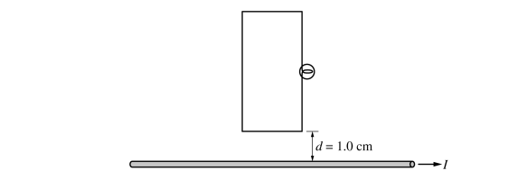
(e) Later, the same rectangular loop with lightbulb is rotated such that a short side of the loop is 1.0 cm above and parallel to the long current-carrying wire, as shown. The current in the wire is again initially flowing from left to right and given by I(t ) = C − Dt, where C = 10.0 A and D = 2.0 A/s. The current through the lightbulb in the loop’s new orientation at time t = 3.0s is \(I_{2}\) . Which of the following correctly relates the current \(I_{2}\) to \(I_{1}\) the current through the lightbulb in part (c)?
___\(I_{2}\) < \(I_{1}\) ___\(I_{2}\) = \(I_{1}\) ___ \(I_{2}\) > \(I_{1}\)
Justify your answer.
▶️Answer/Explanation
3(a) Example Response
Because the current in the straight wire is decreasing, the magnetic field, which is originally pointing out of the page, is decreasing. Hence, the induced current produces a field that is directed out of the page to compensate for the decreasing flux.
3(b) Example Response
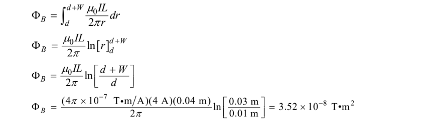
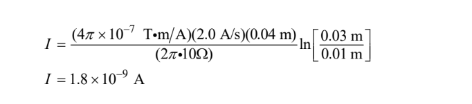
3(c) Example Response
3(d) Example Response
If the current in the wire changes at a faster rate, there will be a greater rate of change of magnetic flux. So the induced emf and current will be higher.
3(e) Example Response
With the new orientation, some parts of the rectangle are further away from the straight wire, which means that the magnetic flux through the rectangle will be less. The rate of change of the flux has the same dependence on distance and will also decrease, resulting in a smaller current.