Question 1
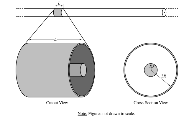
1. A very long nonconducting cylinder is surrounded by a thin concentric conducting cylindrical shell, as shown in the cutout view. A segment of length L of the inner cylinder has a net charge of +Q uniformly distributed throughout its volume. A segment of length L of the outer shell has a net charge of +4Q. The radii of the inner cylinder and outer shell are R and 3R, respectively, as shown in the cross-section view.
(a) Determine the charge on the outer surface of the cylindrical shell within length L.
(b) Using Gauss’s law, derive an expression for the electric field a distance r from the center of the inner cylinder for r < R. Express your answers in terms of Q, R, r, L, and physical constants, as appropriate.
(c) The magnitude of the electric field at r = R is 12 N / C. Calculate the value of the electric field at r = 2R.
(d) Derive an expression for the absolute value of the potential difference between the surface of the nonconducting cylinder and the inner surface of the cylindrical shell.
(e)
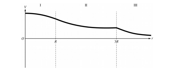
i. On the following axes that include regions I, II, and III, sketch the graph of the electric field E as a function of the distance r from the axis of the inner cylinder.
ii. On the following axes that include regions I, II, and III, sketch the graph of the electric potential V as a function of the distance r from the axis of the inner cylinder.
▶️Answer/Explanation
1(a) Example Response
\( q_{net} = q_{inner} + q_{outer}\)
\( q_{outer} = q_{net} – q_{inner}\)
\( q_{outer} = +4Q – (-Q)\)
\( q_{outer} = +5Q\)
1(b) Example Response
\(E = q_{enc\frac{1}{\varepsilon _{0}(2\pi rL)}} = (Q\frac{r^{2}}{R^{2}})\frac{1}{\varepsilon _{0}(2\pi rL)}\)
\(E = Q\frac{r}{2\pi \varepsilon _{0}R^{2}L}\)
1(c) Example Response
\( E_{new} =\frac{E_{old}}{2} = \frac{12N/C}{2}\)
\( E_{new} = 6 N/C\)
1(d) Example Response
\(\Delta V = -\frac{Q}{2\pi \varepsilon _{0}L}\left [ In(r) \right ]^{r = 3R}_{r = R} = -\frac{Q}{2\pi \varepsilon _{0}L}[In(3R) – In(R)]\)
\(\Delta V = -\frac{Q}{2\pi \varepsilon _{0}L}In(3)\)
1(e)(i) Example Response
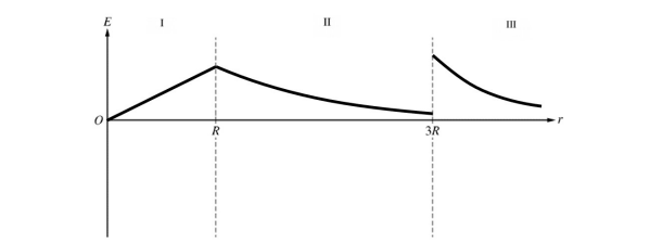
1(e)(ii) Example Response
Question 2
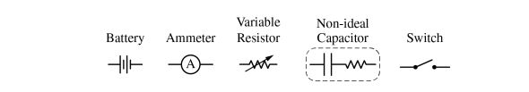
2. A non-ideal capacitor has internal resistance that can be modeled as an ideal capacitor in series with a small resistor of resistance \(r_{C}\) . A group of students performs an experiment to determine the internal resistance of a capacitor. A circuit is to be constructed with the following available equipment: a single ideal battery of potential difference \(\Delta V_{o}\) , a single ammeter, a single variable resistor of resistance R, a single uncharged non-ideal capacitor of capacitance C, and one or more switches as needed.
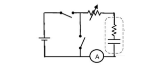
(a) Using the symbols shown, draw a schematic diagram of a circuit that can charge the capacitor and may also be used to study the current through the capacitor as it discharges through the resistor.
The capacitor is fully charged by the battery. At time t = 0, the capacitor starts discharging through the resistor.
(b) Show that the current I through the capacitor as a function of time t is I(t) = I_{0}e^{\frac{-t}{R + r_{c}}C} as the capacitor discharges.
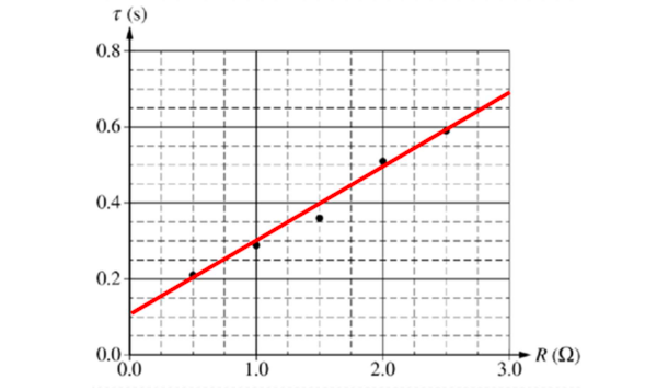
(c) The students determine the time constant \(\tau \) for the circuit as a function of the resistance R. The students’ data are shown in the following graph.
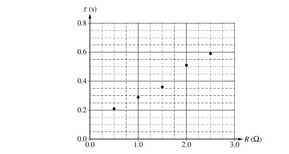
i. Draw the best-fit line for the data.
ii. Using the best-fit line, calculate a value for the internal resistance \(r_{C}\) of the capacitor.
(d) The ammeter is found to be nonideal. Is the actual value for the internal resistance \(r_{C}\) for the capacitor greater than, less than, or equal to the experimental internal resistance of the capacitor calculated in part (c)?
___ Greater than ___ Less than ___ Equal to
Briefly justify your answer using features of the graph in part (c).
(e) The values of the variable resistor in the original experiment ranged from 0.5 Ω to 2.5 Ω. The experiment is repeated with values ranging from 3.0 Ω to 6.0 Ω. Would the slope of the best-fit line be more steep, be less steep, or remain unchanged compared to the graph in part (c)?
___ More steep ___ Less steep ___ Remain unchanged
Briefly justify your answer.
▶️Answer/Explanation
2(a) Example Response
2(b) Example Response
\( \frac{dq}{dt} \frac{I}{C} = (R + r_{c})\frac{dI}{dt} -I\frac{I}{c} = (R + r_{c}) \frac{dI}{dt}; I = -\frac{dq}{dt} \)
Where q is the charge on one plate of the capacitor that decreases over time
\(\frac{I}{I}\frac{dI}{dt} = \frac{-1}{C(R + r_{c})}\)
\(In \frac{I}{I_{0}} = \frac{-t}{C(R + r_{c})} \)
\(I = I_{0}e^{\frac{-t}{C(R+ r_{c})}}\)
2(c) (i) Example Response
2(c) (ii) Example Response
Vertical intercept = \(\tau _{0} = r_{C}C\)
Vertical intercept = 0.08 s
\(r_{C} \frac{vertical\\\ intercept}{C}\)
= \(\frac{0.08 s}{0.2 F}\)
\(r_{C} = 0.4\Omega\)
2(d) Example Response
The internal resistance of the ammeter would add to the internal resistance of the capacitor due to the fact the circuit elements are in series; this would result in an equivalent resistance that is measured in this experiment. Thus, the internal resistance of the capacitor is smaller than this equivalent resistance measured.
2(e) Example Response
The relationship between the time constant and the resistance, the slope, is the capacitance, which does not change regardless of how large the value of the resistance is.
Scoring Note: This point is scored with consistency with the circuit drawn in part (a).
Question 3
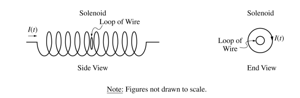
3. A single loop of wire with resistance 3.0 Ω and radius 0.10 m is placed inside a solenoid, with the normal to the loop parallel to the axis of the solenoid. The solenoid has 500 turns, is 0.25 m long, and is connected to a power supply that is not shown. At time t = 0, the power supply is turned on, and the current I in the solenoid as a function of t is given by the equation I(t) = \(\beta t\) , where \(\beta \)= 5.0 A/s. The direction of the current in the solenoid is clockwise, as shown in the end view.
(a) At time t = 2.0 s, is the induced current in the loop, as seen from the end view shown, clockwise, counterclockwise, or zero?
___ Clockwise ___ Counterclockwise ___ Zero
Justify your answer.
(b) Calculate the current in the loop of wire at time t = 2.0 s
(c) Calculate the total energy dissipated by the loop of wire from time t = 0 to time t = 2.0 s.
(d) A group of students attempts to verify experimentally the calculation of the current from part (b). The current in the inner circular loop at time t = 2.0 s is measured to be less than the current calculated in part (b). Which of the following could explain this discrepancy? Select one answer.
___ The experiment did not account for Earth’s magnetic field.
___ The plane of the loop is not perpendicular to the axis of the solenoid.
___ The center of the loop is not on the axis of the solenoid.
___ The resistance of the loop is less than the given value.
___ The radius of the loop is actually larger than 0.10 m.
Justify your answer.
(e) The power supply is now turned off. The original loop of wire is then replaced with a second loop made from wire that has the same thickness and is made from the same material as the original loop of wire. The second loop has radius 0.20 m, is placed in the same orientation as the original loop, and fits completely inside the solenoid. The power supply is turned on, and the current I in the solenoid as a function of t is again given by the equation I(t) = \(\beta t\) , where \(\beta \) = 5.0 A/s. Which of the following expressions correctly indicates the ratio \(\frac{I_{2}}{I_{1}}\) where \(I_{1}\) represents the current induced in the original loop of wire in part (b) and \(I_{2}\) represents the current induced in the second loop of wire?
\(\frac{I_{2}}{I_{1}} = 1\) I < \(\frac{I_{2}}{I_{1}}\) < 2 \(\frac{I_{2}}{I_{1}} = 2\) \(\frac{I_{2}}{I_{1}}\) > 2
Justify your answer
▶️Answer/Explanation
3(a)Example Response
In the end view, the magnetic field due to the solenoid is directed into the page. The current in the solenoid is increasing; thus, the magnetic flux is increasing. According to Lenz’s law, because the magnetic flux is increasing and into the page, the current in the loop must create a magnetic field directed out of the page; thus, the current in the loop must be counterclockwise the counter the change in magnetic flux.
3(b)Example Response
\( I_{loop} = \frac{\left ( 4\pi \times 10^{-7} T.m/A \right )
\frac{500\\\ turns}{0.25 m}((\pi )(0.10 m)^{2})}{(3\Omega )} (5.0 A/s) = 1.3 \times 10^{-4} A\)
3(c)Example Response
\(P = \frac{dE}{dt} =\frac{\Delta E}{\Delta t} \therefore \Delta E = P\Delta t\)
\(\Delta E = (5.2 \times 10^{-8}W)(2.0 s) = 1.0 \times 10^{-7} J\)
3(d)Example Response
If the plane of the loop is not perpendicular to the axis of the solenoid it is not perpendicular to the magnetic field. Therefore, the magnetic flux and emf will be less, so the current will be less.
3(e)Example Response
The magnetic flux quadruples. This is because of the increase in area of the loop, which quadruples the emf. The resistance of the loop doubles because the length of the wire doubles. Therefore, \(\frac{I_{2}}{I_{1}} \) = 2.
\(\varepsilon = \mu _{0}n(A_{loop}) = \mu _{0}n(\pi r^{2})\frac{dI}{dt}\)
The radius of the loop doubles. Therefore, the area of the loop quadruples.
\(R=\rho \frac{2\pi r}{A_{wire}}\)
The radius of the loop doubles. Therefore, the resistance of the loop doubles.
\(\frac{I_{2} = \frac{\varepsilon }{R} = \frac{\mu _{0}n(4)A}{(2)R}\frac{dI}{dt}}{I_{1} = \frac{\varepsilon }{R} = \frac{\mu _{0}nA}{R}\frac{dI}{dt}} = 2\)