Question 1
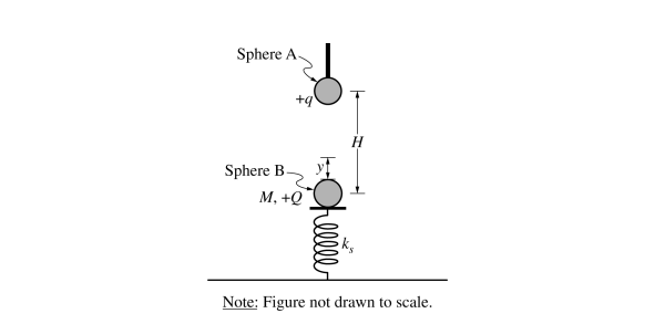
1. Students perform an experiment to determine the value of vacuum permittivity \(\varepsilon _{o}\) . Sphere A is nonconducting with charge +q and is attached to an insulating rod. Sphere B is nonconducting with charge +Q, and has mass M . Sphere B rests on an insulating platform of negligible mass that is attached to a vertical ideal spring with spring constant \(K_{s}\) .
Sphere B and the spring are initially at rest. Sphere A is then brought near Sphere B without touching. When the centers of the spheres are separated by a vertical distance H, the spring has been compressed a distance y, as shown in the figure. The students measure y for different values of H.
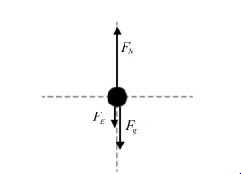
(a) On the following dot that represents Sphere B in the figure on the previous page, draw and label the forces (not components) that are exerted on Sphere B. Each force must be represented by a distinct arrow starting on, and pointing away from, the dot.

(b) Derive the relationship between y and H to show that \(y = \frac{1}{4\pi \varepsilon _{0}} \frac{Qq}{k_{s}H^{2}} + \frac{Mm}{k_{s}}\)
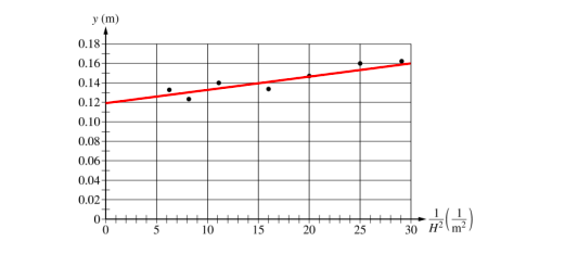
(c) The students plot collected data of y as a function of \(\frac{1}{H^{2}}\) , as shown in the graph.
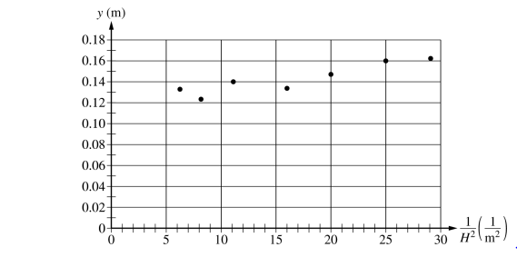
i. Draw the best-fit line for the data.
ii. Using the best-fit line, calculate an experimental value for the vacuum permittivity\( \varepsilon _{O} \) when\(Q=q=2.00\times 10^{-6}C \ and \ K_{s}=25N\setminus m\) .
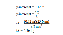
iii. Using the best-fit line, calculate an experimental value for the mass of Sphere B
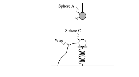
(d) The students modify the experiment by replacing nonconducting Sphere B with conducting Sphere C that has the same charge +Q and mass M . Sphere A is brought near Sphere C without touching, compressing the spring. Sphere C comes to rest.
i. In the original experiment, when the centers of spheres A and B are a vertical distance \(H_{1}\) apart, the spring is compressed a distance \(y_{1}\) . In the modified experiment, when the centers of spheres A and C are a vertical distance \(H_{1}\) apart, the spring is compressed a distance \(y_{2}\) .
Is \(y_{2}\) greater than, less than, or equal to \(y_{1}\) ?
____ \(y_{2}\) > \(y_{1}\) ____ \(y_{2}\) < \(y_{1}\) ____ \(y_{2}\) = \(y_{1}\)
Justify your answer.
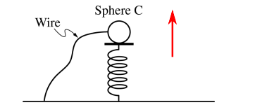
ii. Sphere C is then grounded with a wire. On the following figure, draw an arrow indicating the direction that the platform will move immediately after being grounded. If the platform remains stationary, write “does not move.”
▶️Answer/Explanation
1(a) Example Response
1(b) Example Response
\(F_{N} – F_{E} – F_{g} = 0\)
\(F_{N} – F_{E} – F_{g}\)
\(k_{s}y = \frac{1}{4\varepsilon \mu _{0}} \frac{Qq}{H^{2}} + Mg\)
\(y = \frac{1}{4\varepsilon \mu _{0}} \frac{Qq}{k_{s}H^{2}} + \frac{Mg}{k_{s}}\)
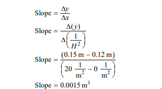
1(c) (i) Example Response
1(c) (ii) Example Response
1(c) (iii) Example Response
1(d) (i) Example Response
\(y_(2)\) < \(y_(1)\) , Charges are now free to move within Sphere C now that it is a conducting sphere. Electrons on Sphere C will be attracted to the excess positive charges on Sphere A and move closer to Sphere A . This leaves the opposite side of Sphere C more positively charged which results in less electric repulsion between the spheres and as a result less compression in the spring.
1(d) (ii) Example Response
Question 2
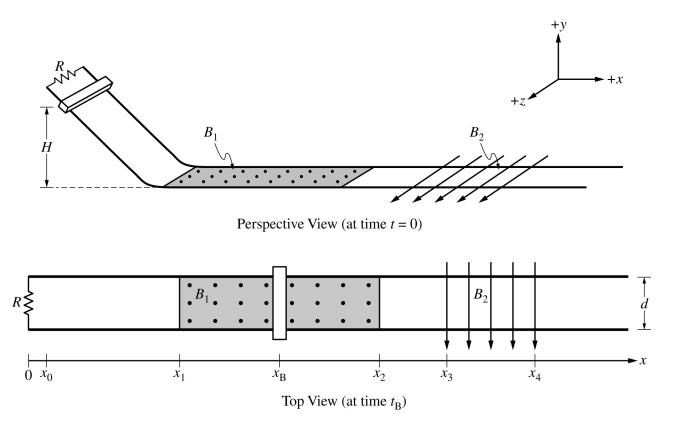
2. Two parallel conducting rails are separated by distance d = 0.30 m. A resistor of resistance R = 0.20 Ω connects the rails. A conducting bar is placed on a sloped section of the rails at height H above the horizontal section of the rails. Frictional forces and the resistances of the bar and rails are negligible.
• At time t = 0, the bar is released from rest from position \(x_{o} and slides down the sloped section of the rails, as shown in the Perspective View.
• At time \(t_{1}\) , the bar reaches position \(x_{1}\) and smoothly transitions to the horizontal section of the rails and enters a uniform magnetic field of magnitude \(B_{1}\) = 0.40 T that is directed in the +y-direction.
• At time \(t_{2}\) , the bar reaches position \(x_{2}\) and enters a region with no magnetic field.
• At time \(t_{3}\) , the bar reaches position \(x_{3}\) and enters a uniform magnetic field of magnitude \(B_{2}\) = 0.60 T that is directed in the +z-direction.
• At time \(t_{4}\), the bar reaches position \(x_{4}\) and enters a region with no magnetic field. The bar is at position \(x_{B}\) (shown in Top View) at time \(t_{B}\) such that \(t_{1}\) < \(t_{B}\) < \(t_{1}\) .
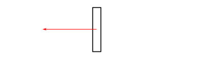
(a) On the following diagram of the bar, as observed from the Top View, draw an arrow indicating the direction of the net force \(F_{net}\) exerted on the bar at time \(t_(B)\) . If the net force is zero, write \(F_{net}\)= 0 .

(b) At time \(t_(B)\) , the speed of the bar is v = 2.5 m/s.
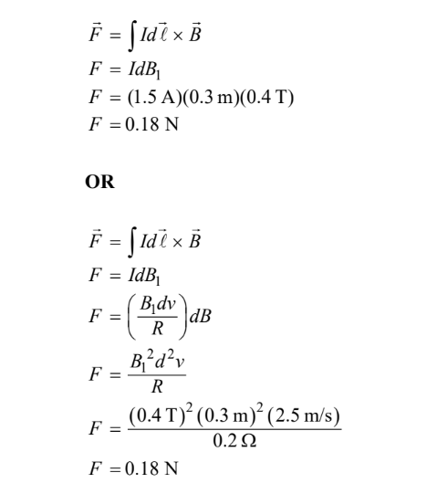
i. Calculate the magnitude of the current in the bar at time \(t_(B)\).
ii. Calculate the magnitude of the net force \(F_{net}\) exerted on the bar at time \(t_{B}\).
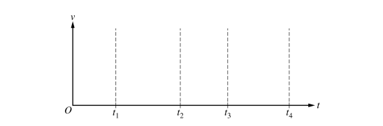
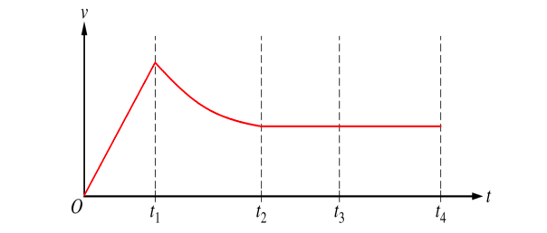
(c) On the following axes, sketch a graph of the speed v of the bar as a function of time t between t = 0 and \(t_{4}\).
(d) The original scenario is repeated but with a new bar that has the same mass but with a nonnegligible resistance R = 0.20 Ω. The new bar is released from rest and smoothly transitions to the horizontal section of
the rails and enters the first uniform magnetic field.
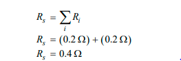
i. Determine the total resistance of the closed circuit.
ii. In the original scenario, the magnitude of the acceleration of the bar immediately after the bar enters the first uniform magnetic field is \(a_{original}\). In the new scenario, the magnitude of the acceleration of the bar immediately after the bar enters the first uniform magnetic field is \(a_{new}\). Is \(a_{new}\) greater than, less than, or equal to \(a_{original}\) ? Justify your answer.
(e) Describe a modification to H, \(B_{1}\), or d that will result in a larger induced current in the new bar immediately after the bar enters the first uniform magnetic field. Justify your answer.
▶️Answer/Explanation
2(a) Example Response
2(b)(i) Example Response
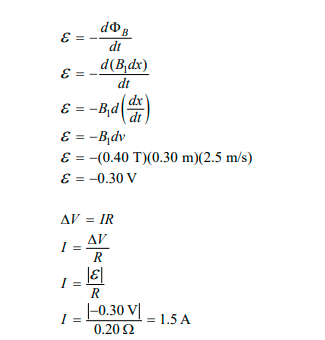
2(b)(ii) Example Response
2(c) Example Response
2(d) (i) Example Response
2(d) (ii) Example Response
The new acceleration \(a_{new}\) is less than \(a_{original}\). Greater resistance of the bar causes the current to be less than in the original scenario. Less current causes the magnetic force F= IdB on the bar to also be less than the original. By Newton’s second law F= ma so less force on a bar of the same mass results in less acceleration.
2(e) Example Response
Increasing H will increase the induced current. If the ramp is higher, then the potential energy is greater and this results in greater kinetic energy and greater velocity at the bottom of the ramp. A greater velocity causes a greater rate of change in flux as the bar moves through the field. By Faraday’s law the emf is greater and therefore also the current.
OR
Increasing \(B_{1}\) will increase the induced current. If the magnetic field is stronger this increases the flux through the circuit and therefore also the rate of change in the flux. By Faraday’s law the emf is then greater and therefore also the current.
OR
Increasing d will increase the induced current. A larger width results in a greater area encompassed by the circuit. Greater area increases the flux through the circuit and therefore also the rate of change in the flux. By Faraday’s law the emf is then greater and therefore also the current.
Question 3
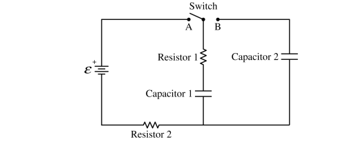
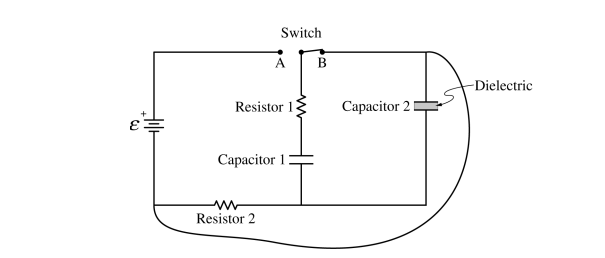
3. The circuit shown consists of an ideal battery of emf Ɛ, resistors 1 and 2 each with resistance R, capacitors 1 and 2 each with capacitance C, and a switch. The switch is initially open and both capacitors are uncharged.
At time t = 0, the switch is closed to Position A.
(a) Write, but do NOT solve, a differential equation that can be used to determine the charge Q on the positive plate of Capacitor 1 as a function of time t after the switch is closed to Position A. Express your answer in
terms of Ɛ, R, C, Q, t, and fundamental constants, as appropriate.
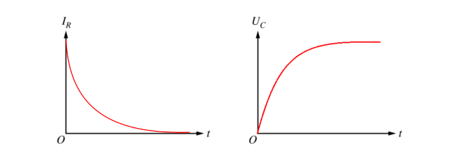
(b) On the axes shown, sketch graphs of the current \(I_{R}\) in Resistor 1 and the energy \(U_{C}\) stored in Capacitor 1 as functions of time t from time t = 0 until steady-state conditions are nearly reached.
A long time after the switch is closed to Position A, the total charge on the positive plate of Capacitor 1 is \(Q_{o}\) and Capacitor 2 is uncharged. (c) At time \(t_{1}\), the switch is closed to Position B.
i. Immediately after \(t_{1}\), is the direction of the current in Resistor 1 directed up, directed down, or is there no current? Briefly justify your answer.
ii. Determine an expression for the total charge on the positive plate of Capacitor 2 a long time after \(t_{1}\). Express your answer in terms of \(Q_{o}\) and fundamental constants, as appropriate.
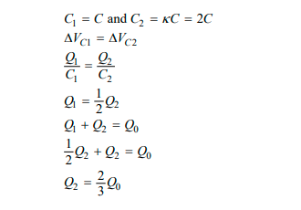
iii. Derive an expression for the total energy dissipated by Resistor 1 immediately after time \(t_{1}\) until new steady-state conditions have been reached. Express your answer in terms of C, \(Q_{o}\) , and fundamental constants, as appropriate. With the switch still closed to Position B, a dielectric material with dielectric constant k = 2 is inserted between the plates of Capacitor 2.
(d) Determine the charge on the positive plate of Capacitor 2 a long time after the dielectric has been inserted. Express your answer in terms of \(Q_{o}\) and fundamental constants, as appropriate.
With the switch still closed to Position B, a wire of negligible resistance is connected between two corners of the circuit, as shown.
(e) Express your answers to part (e)(i) and part (e)(ii) in terms of R, C, \(Q_{o}\) , and fundamental constants, as appropriate.
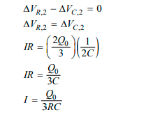
i. Derive an expression for the current in Resistor 2 immediately after the wire is connected to the circuit.
ii. Determine the current in Resistor 2 a long time after the wire is connected to the circuit.
3(a) Example Response
\(\varepsilon -\Delta V_{c} – \Delta V_{R,eq} = 0\)
\(\varepsilon -\frac{Q}{C} -2R\frac{dQ}{dt} = 0\)
3(b) Example Response
3(c) (i) Example Response
When the switch is closed at time \(t_(1)\) , positive charge has built up on the top plate of the capacitor. This positive charge on the top plate pushes charge up through Resistor 1 and down through Capacitor 2 to charge Capacitor 2 .
OR
After a long-time the top plate of Capacitor 1 is at a high potential due to its being charged by the battery. When the switch is closed at time \(t_(1)\) , the resulting current is up through Resistor 1 as the current goes from high potential on the top plate to low potential clockwise around the circuit through Capacitor 2 .
3(c) (ii) Example Response
The potential difference across Capacitor 1 is equal to the potential difference across Capacitor 2 . Capacitor 2 has the same capacitance of Capacitor 1. Therefore, Capacitor 2 stores the same charge that is stored on Capacitor 1. Due to conservation of charge, Capacitor 2 stores half of the original charge equal to \(\frac{Q_{o}}{2}\).
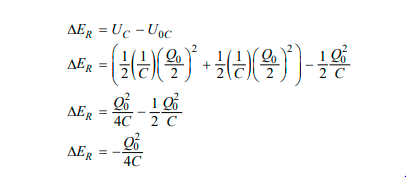
3(c) (iii) Example Response
3(d) Example Response
3(e) (i) Example Response
3(e) (ii) Example Response
For indicating that the current is zero