Question 1


Diagram \( \mathrm{A} \) shows an energy bar chart that represents the gravitational potential energy \( U_g \) of the block-Earth system and the kinetic energy \( K \) of the block at Point \( A \), when the block is released from rest at height \( 6R \).
• Represent any energy that is equal to zero with a distinct line on the zero-energy line.
• The relative height of each shaded region should reflect the magnitude of the respective energy consistent with the scale used in Diagram \( \mathrm{A} \).

Most-appropriate topic codes (AP Physics 1):
• Topic \( 3.3 \) — Potential Energy (Part \( \mathrm{(a)} \), Part \( \mathrm{(b)} \))
• Topic \( 3.4 \) — Conservation of Energy (Part \( \mathrm{(a)} \), Part \( \mathrm{(b)} \), Part \( \mathrm{(c)(ii)} \))
• Topic \( 2.2 \) — Forces and Free-Body Diagrams (Part \( \mathrm{(c)(i)} \))
• Topic \( 2.9 \) — Circular Motion (Part \( \mathrm{(c)(i)} \), Part \( \mathrm{(c)(ii)} \))
▶️ Answer/Explanation
(a)
At Point \( A \), the block is released from rest, so all of the mechanical energy is gravitational potential energy.
Since Point \( A \) is at height \( 6R \), the total energy is proportional to \( 6R \). At Point \( B \), the block is at height \( 2R \), so
\( U_g = Mg(2R) \)
and the remaining energy must be kinetic energy:
\( K = Mg(6R) – Mg(2R) = 4MgR \)
So in Diagram \( \mathrm{B} \), the \( U_g \) bar should have height \( 2 \) units and the \( K \) bar should have height \( 4 \) units, for a total of \( 6 \) units.
This keeps the total mechanical energy the same as in Diagram \( \mathrm{A} \).
(b)
Start with conservation of mechanical energy:
\( E_i = E_f \)
At Point \( A \):
\( E_i = U_{g,A} = Mg(6R) \)
At Point \( B \):
\( E_f = U_{g,B} + K_B = Mg(2R) + \dfrac{1}{2}Mv_B^2 \)
Therefore,
\( Mg(6R) = Mg(2R) + \dfrac{1}{2}Mv_B^2 \)
\( 6gR = 2gR + \dfrac{1}{2}v_B^2 \)
\( 4gR = \dfrac{1}{2}v_B^2 \)
\( v_B^2 = 8gR \)
\( \boxed{v_B = \sqrt{8gR}} \)
The mass cancels, which is what we expect for frictionless motion under gravity.
(c)(i)
At Point \( C \), the forces on the block are:
• A downward gravitational force \( F_g \)
• A downward normal force \( F_N \)
Both arrows should point downward from the dot because at the top of the loop, the center of the circular path is below the block, so the normal force points toward the center, which is downward.

(c)(ii)
The claim is incorrect because if the block starts from height \( 4R \), then by energy conservation it would reach Point \( C \) with zero kinetic energy.
Point \( C \) is also at height \( 4R \), so starting from \( 4R \) means
\( Mg(4R) = Mg(4R) + \dfrac{1}{2}Mv_C^2 \)
which gives
\( v_C = 0 \)
But to remain in contact with the track at the top of the loop, the block must still have some speed so that a centripetal force can be provided. If the speed is zero, the block does not have enough momentum to stay on the track and will lose contact.
So the minimum starting height must be greater than \( 4R \), not equal to \( 4R \).
Question 2
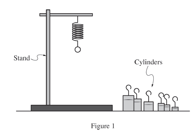
A student hangs a spring of unknown spring constant \( k \) vertically by attaching one end to a stand, as shown in Figure \( 1 \). The other end of the spring has a small loop from which small cylinders can be hung. In addition to the spring, the student has access only to a variety of cylinders of unknown masses, a stopwatch, and a digital scale.


In a different experiment, the student attaches one end of a spring to a force sensor that is attached to a wall. The other end of the spring is attached to a cart with mass \( m = 0.25\ \mathrm{kg} \). The student places a motion detector to the right of the cart, as shown in Figure \( 2 \), and pulls the cart to the right a small distance so that the spring is stretched. The student releases the cart from rest, and the cart-spring system oscillates.

Most-appropriate topic codes (AP Physics 1):
• Topic \( 7.3 \) — Representing and Analyzing SHM (Part \( \mathrm{(b)} \), Part \( \mathrm{(c)} \))
• Topic \( 7.4 \) — Energy of Simple Harmonic Oscillators (Part \( \mathrm{(c)(i)} \))
• Topic \( 4.2 \) — Change in Momentum and Impulse (Part \( \mathrm{(c)(ii)} \), Part \( \mathrm{(c)(iii)} \))
• Topic \( 3.1 \) — Translational Kinetic Energy (Part \( \mathrm{(c)(i)} \))
▶️ Answer/Explanation
(a)
One valid method is to use the period of oscillation of the spring-cylinder system for several different hanging masses.
| Quantity to Be Measured | Symbol for Quantity | Equipment for Measurement |
|---|---|---|
| Mass of a cylinder | \( m \) | Digital scale |
| Time for \( N \) oscillations | \( t_N \) | Stopwatch |
| Number of oscillations counted | \( N \) | Direct count |
Procedure:
First, choose one cylinder and use the digital scale to measure its mass \( m \). Hang that cylinder from the spring. Pull it down a small distance and release it so that it oscillates vertically.
Use the stopwatch to measure the total time \( t_N \) for \( N \) complete oscillations. Then calculate the period using
\( T = \dfrac{t_N}{N} \)
Repeat this process for several cylinders of different masses, recording a set of \( (m,T) \) values.
To reduce uncertainty, time many oscillations instead of just one, repeat the timing trials for each mass, and average the measured values of \( T \). Also keep the oscillations small so the motion stays close to simple harmonic motion.
(b)(i)
One valid choice is:
Vertical axis: \( m \)
Horizontal axis: \( T^2 \)
Since
\( T = 2\pi \sqrt{\dfrac{m}{k}} \)
squaring gives
\( T^2 = \dfrac{4\pi^2 m}{k} \)
Rearranging,
\( m = \left(\dfrac{k}{4\pi^2}\right) T^2 \)
so this graph is linear.
(b)(ii)
For a graph of \( m \) versus \( T^2 \), the slope is
\( \text{slope} = \dfrac{k}{4\pi^2} \)
Therefore,
\( k = (\text{slope})\,4\pi^2 \)
So the spring constant is found by multiplying the slope of the best-fit line by \( 4\pi^2 \).
(c)(i)
Use
\( K = \dfrac{1}{2}mv^2 \)
From the velocity-time graph:
\( v_i \approx 0.30\ \mathrm{m/s} \) at \( t = 0.5\ \mathrm{s} \)
\( v_f \approx 0 \) at \( t = 2.0\ \mathrm{s} \)
\( \Delta K = K_f – K_i \)
\( \Delta K = \dfrac{1}{2}(0.25)(0)^2 – \dfrac{1}{2}(0.25)(0.30)^2 \)
\( \Delta K = 0 – 0.01125\ \mathrm{J} \)
\( \boxed{\Delta K \approx -0.0113\ \mathrm{J}} \)
(c)(ii)
The change in momentum is approximately
\( \boxed{0\ \mathrm{kg \cdot m/s}} \)
The change in momentum equals the impulse, which is the area under the force-time graph:
\( \Delta p = \int F\,dt \)
From \( t = 0.5\ \mathrm{s} \) to \( t = 2.5\ \mathrm{s} \), the negative area and positive area under the curve are approximately equal in magnitude, so they cancel. Therefore the net impulse, and thus the change in momentum, is about zero.
(c)(iii)
Yes, the velocity-time graph confirms this estimate.
At \( t = 0.5\ \mathrm{s} \), the velocity is about \( 0.30\ \mathrm{m/s} \), and at \( t = 2.5\ \mathrm{s} \), the velocity is also about \( 0.30\ \mathrm{m/s} \).
Since momentum is
\( p = mv \)
and the mass of the cart is the same at both times, the momentum is the same at both times. Thus,
\( \Delta p = 0 \)
which agrees with the estimate from the force-time graph.
Question 3


Most-appropriate topic codes (AP Physics 1):
• Topic \( 5.4 \) — Torque and the Second Condition of Equilibrium (Part \( \mathrm{(b)} \), Part \( \mathrm{(c)} \), Part \( \mathrm{(d)} \))
• Topic \( 5.5 \) — Rotational Equilibrium and Newton’s First Law in Rotational Form (Part \( \mathrm{(b)} \), Part \( \mathrm{(c)} \))
• Topic \( 5.6 \) — Newton’s Second Law in Rotational Form (Part \( \mathrm{(c)} \), Part \( \mathrm{(e)} \))
• Topic \( 6.2 \) — Torque and Work (Part \( \mathrm{(e)} \))
▶️ Answer/Explanation
(a)
Three forces act on the beam:
\( \bullet \) The gravitational force \( F_g = Mg \), acting downward at the center of the beam
\( \bullet \) The tension force \( F_T \), acting at the right end of the beam along the string, directed upward and leftward
\( \bullet \) The hinge force \( F_H \), acting at the hinge
A correct free-body diagram therefore has one downward arrow at the center, one up-left arrow at the right end, and one force arrow at the hinge.

(b)
\( \boxed{F_{T2} > F_{T1}} \)
The beam remains horizontal and in rotational equilibrium in both cases, so the torque produced by the string must balance the torque produced by the beam’s weight.
When the string is attached lower on the wall, the angle \( \theta \) becomes smaller. That means the perpendicular component of the tension is smaller for the same tension. To produce the same balancing torque, the tension must therefore be larger.
So a smaller string angle requires a larger tension.
(c)
Start with Newton’s second law for rotation:
\( \sum \tau = I\alpha \)
Since the beam is in equilibrium,
\( \alpha = 0 \qquad \Rightarrow \qquad \sum \tau = 0 \)
Take torques about the hinge so the hinge force produces no torque.
The torque due to the tension has magnitude
\( \tau_T = (F_T \sin\theta)L \)
because the tension acts at the end of the beam, a distance \( L \) from the hinge, and only the perpendicular component contributes.
The torque due to the beam’s weight has magnitude
\( \tau_g = Mg\left(\dfrac{L}{2}\right) \)
because the weight acts at the center of mass of the uniform beam, halfway along its length.
Setting the net torque equal to zero:
\( (F_T \sin\theta)L – Mg\left(\dfrac{L}{2}\right) = 0 \)
\( (F_T \sin\theta)L = Mg\left(\dfrac{L}{2}\right) \)
Cancel \( L \):
\( F_T \sin\theta = \dfrac{Mg}{2} \)
Therefore,
\( \boxed{F_T = \dfrac{Mg}{2\sin\theta}} \)
This result shows that the tension depends inversely on \( \sin\theta \).
(d)
Yes, the derived equation is consistent with the reasoning in part \( \mathrm{(b)} \).
From \( F_T = \dfrac{Mg}{2\sin\theta} \), the tension is inversely proportional to \( \sin\theta \). When the string is attached lower, the angle decreases from \( \theta_1 \) to \( \theta_2 \), so \( \sin\theta \) becomes smaller.
A smaller denominator makes \( F_T \) larger, so the equation predicts \( F_{T2} > F_{T1} \), exactly matching the qualitative argument in part \( \mathrm{(b)} \).
(e)
The angular speed starts at \( 0 \) when the string is cut, then increases as the beam falls.
The graph should be monotonically increasing and concave down.
Early in the motion, the beam speeds up quickly because the gravitational torque is relatively large. As the beam approaches vertical, the lever arm of the weight decreases, so the torque and angular acceleration decrease. Therefore the angular speed continues to increase, but at a decreasing rate.

Question 4

Most-appropriate topic codes (AP Physics 1):
• Topic \( 3.3 \) — Potential Energy (Part \( \mathrm{(a)} \))
• Topic \( 7.1 \) — Defining Simple Harmonic Motion (SHM) (Part \( \mathrm{(b)} \))
• Topic \( 7.2 \) — Frequency and Period of SHM (Part \( \mathrm{(b)} \))
• Topic \( 8.1 \) — Internal Structure and Density (Part \( \mathrm{(a)} \), Part \( \mathrm{(b)} \), through gravitational field strength)
• Topic \( 2.6 \) — Gravitational Force (Part \( \mathrm{(a)} \), Part \( \mathrm{(b)} \))
▶️ Answer/Explanation
(a)
On Planet \( X \), the radius is greater while the planet’s mass is the same as Earth’s, so the gravitational field strength is smaller.
Because the sphere is released from the same angle \( \theta \), it travels through the same vertical distance from \( A \) to \( B \) in both situations. The work done by gravity depends on the gravitational force and the vertical displacement.
Since the downward gravitational force on the sphere is smaller on Planet \( X \), but the vertical distance traveled is the same, the work done by gravity is smaller. Therefore,
\( \boxed{W_X < W_E} \)
Equivalently, the decrease in gravitational potential energy from \( A \) to \( B \) is smaller on Planet \( X \) because \( g \) is smaller there.
(b)
The period of a simple pendulum is given by
\( T = 2\pi \sqrt{\dfrac{L}{g}} \)
On Planet \( Y \), the planet’s radius is the same as Earth’s but its mass is larger, so the gravitational field strength \( g \) is larger. If the string length stayed the same, the larger value of \( g \) would make the period smaller, because \( g \) is in the denominator. That would make \( T_Y < T_E \).
However, this new string is slightly elastic, so its length can change when the tension changes. On Planet \( Y \), the sphere has greater weight, so the tension in the string can be larger. That larger tension could stretch the string and increase its length \( L \). Since the period increases with \( L \), a large enough increase in string length could outweigh the effect of the larger \( g \), making the period longer instead. In that case, \( T_Y > T_E \).
So \( T_Y \) could be smaller than \( T_E \) because of the larger gravitational field strength, or it could be larger than \( T_E \) if the increased tension stretches the elastic string enough to increase the pendulum length significantly.
Question 5

At time \( t=0 \), Block \( A \) slides along a horizontal surface toward Block \( B \), which is initially at rest, as shown in Figure \( 1 \). The masses of blocks \( A \) and \( B \) are \( 6\ \mathrm{kg} \) and \( 2\ \mathrm{kg} \), respectively. The blocks collide elastically at \( t=1.0\ \mathrm{s} \), and as a result, the magnitude of the change in kinetic energy of Block \( B \) is \( 9\ \mathrm{J} \). All frictional forces are negligible.

Most-appropriate topic codes (AP Physics 1):
• Topic \( 4.1 \) — Linear Momentum (Part \( \mathrm{(b)} \), Part \( \mathrm{(c)} \))
• Topic \( 4.2 \) — Change in Momentum and Impulse (Part \( \mathrm{(c)} \))
• Topic \( 4.3 \) — Conservation of Linear Momentum (Part \( \mathrm{(b)} \), Part \( \mathrm{(c)} \))
• Topic \( 4.4 \) — Elastic and Inelastic Collisions (Part \( \mathrm{(a)} \), Part \( \mathrm{(c)} \))
• Topic \( 1.3 \) — Representing Motion (Part \( \mathrm{(b)} \))
▶️ Answer/Explanation
(a)
Block \( B \) starts from rest, so its initial kinetic energy is \( 0 \). The change in kinetic energy of Block \( B \) is \( 9\ \mathrm{J} \), so its final kinetic energy must be
\( K_B = 9\ \mathrm{J} \)
Use
\( K = \dfrac{1}{2}mv^2 \)
\( 9 = \dfrac{1}{2}(2)v_B^2 \)
\( 9 = v_B^2 \)
\( v_B = 3\ \mathrm{m/s} \)
Therefore, \( \boxed{v_B = 3\ \mathrm{m/s}} \)
Since the mass of Block \( B \) is only \( 2\ \mathrm{kg} \), a \( 9\ \mathrm{J} \) gain in kinetic energy corresponds to a moderate speed of \( 3\ \mathrm{m/s} \).
(b)
At \( t=1.0\ \mathrm{s} \), all three lines meet at \( x=2\ \mathrm{m} \).
After the collision:
\( \bullet \) Block \( B \) moves to the right with speed \( 3\ \mathrm{m/s} \), so its position line is a straight line with a steeper positive slope than before.
\( \bullet \) Block \( A \) continues moving to the right but with a smaller speed than before, so its position line is a straight line with a positive slope smaller than its pre-collision slope.
\( \bullet \) The center-of-mass line remains a straight line with the same slope as before the collision.
A correct continuation from \( t=1.0\ \mathrm{s} \) to \( t=2.0\ \mathrm{s} \) is:
\( \text{Block }A:\ \) line from \( (1.0,\ 2.0) \) to \( (2.0,\ 3.0) \), so slope \( = 1\ \mathrm{m/s} \)
\( \text{Block }B:\ \) line from \( (1.0,\ 2.0) \) to \( (2.0,\ 5.0) \), so slope \( = 3\ \mathrm{m/s} \)
\( \text{Center of Mass}:\ \) straight line continuing with the same pre-collision slope, from \( (1.0,\ 2.0) \) to about \( (2.0,\ 3.5) \)

The center of mass keeps moving uniformly because there is no net external horizontal force on the two-block system.
(c)
The line for the center of mass would not change.
Even if the collision were inelastic and the blocks stuck together, the total momentum of the two-block system would still be conserved because there is no external horizontal force. The motion of the center of mass depends only on the net external force, not on whether the collision is elastic or inelastic.
So the center-of-mass line would remain the same straight line with the same slope as in part \( \mathrm{(b)} \). In the sticking case, the separate lines for Blocks \( A \) and \( B \) after the collision would merge into one common line, but the center-of-mass line itself would be unchanged.