Question 1
• Indicate the direction of the magnetic force that is exerted on Wire \( 1 \) by Wire \( 2 \) in Figure \( 3 \).
_____ Counterclockwise
_____ There is no induced current in the loop.
Most-appropriate topic codes (AP Physics 2):
• Topic \( 12.4 \) — Electromagnetic Induction and Faraday’s Law (Part \( \mathrm{B} \))
• Skill \( 1.A \) — Create diagrams, tables, charts, or schematics to represent physical situations (Part \( \mathrm{A(i)} \))
• Skill \( 2.A \) — Derive a symbolic expression from known quantities by selecting and following a logical mathematical pathway (Part \( \mathrm{A(ii)} \))
• Skill \( 2.B \) — Calculate or estimate an unknown quantity with units from known quantities, by selecting and following a logical computational pathway (Part \( \mathrm{A(ii)} \))
• Skill \( 3.C \) — Justify or support a claim using evidence from experimental data, physical representations, or physical principles or laws (Part \( \mathrm{B} \))
▶️ Answer/Explanation
A(i)
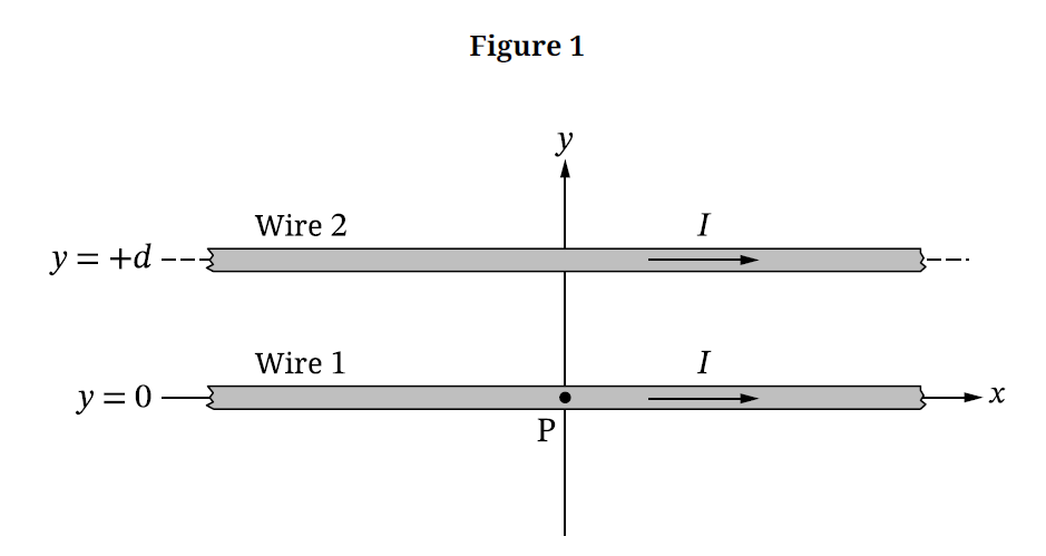
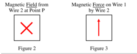
At Point \( P \), the magnetic field due to Wire \( 2 \) is into the page.
Using the right-hand rule for a current in the \( +x \)-direction, the field circles around Wire \( 2 \). Since Point \( P \) is below Wire \( 2 \), the field there points into the page.
The magnetic force on Wire \( 1 \) due to Wire \( 2 \) is in the \( +y \)-direction \( (\text{upward}) \).
Parallel currents in the same direction attract, so Wire \( 1 \) is pulled upward toward Wire \( 2 \).
A(ii)
Start with the magnetic field of a very long straight wire:
\( B=\dfrac{\mu_0 I}{2\pi r} \)
For Wire \( 2 \), the distance from Wire \( 1 \) is \( d \), so the magnetic field magnitude at Wire \( 1 \) is
\( B_2=\dfrac{\mu_0 I}{2\pi d} \)
For Wire \( 3 \), the current is \( 2I \), so at distance \( |y_3| \) from Wire \( 1 \),
\( B_3=\dfrac{\mu_0 (2I)}{2\pi |y_3|} \) \( =\dfrac{\mu_0 I}{\pi |y_3|} \)
Since the net magnetic force on Wire \( 1 \) is zero, the magnetic fields from wires \( 2 \) and \( 3 \) at Wire \( 1 \) must have equal magnitudes and opposite directions. Therefore,
\( \dfrac{\mu_0 I}{2\pi d}=\dfrac{\mu_0 (2I)}{2\pi |y_3|} \)
Canceling common factors gives
\( \dfrac{1}{2d}=\dfrac{1}{|y_3|} \)
so
\( |y_3|=2d \)
To oppose the force from Wire \( 2 \), Wire \( 3 \) must be placed below Wire \( 1 \), so
\( \boxed{y_3=-2d} \)
The sign matters here: placing Wire \( 3 \) above Wire \( 1 \) would make the forces add instead of cancel.
B.
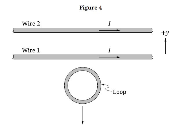
\( \boxed{\text{Clockwise}} \)
Below both wires, the magnetic field from Wire \( 1 \) and Wire \( 2 \) points into the page. As the loop moves farther downward, it moves farther from the wires, so the magnetic field through the loop becomes weaker. Therefore, the magnetic flux into the page decreases.
By Lenz’s law, the induced current must produce a magnetic field that opposes this decrease. So the induced field must also be into the page.
A clockwise current produces a magnetic field into the page, so the induced current is clockwise.
Question 2
_____ \( T_{\mathrm{new}} < T_0 \)
_____ \( T_{\mathrm{new}} = T_0 \)
Most-appropriate topic codes (AP Physics 2):
• Topic \( 9.3 \) — Thermal Energy Transfer and Equilibrium (Part \( \mathrm{A} \), Part \( \mathrm{C} \), Part \( \mathrm{D} \))
• Topic \( 9.4 \) — The First Law of Thermodynamics (Part \( \mathrm{B} \), Part \( \mathrm{C} \), Part \( \mathrm{D} \))
▶️ Answer/Explanation
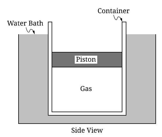
A.
The piston has three forces acting on it:
\( \bullet \) Upward force exerted by the gas, \( F_{\mathrm{gas}} \)
\( \bullet \) Downward weight of the piston, \( F_g = Mg \)
\( \bullet \) Downward force from the atmosphere, \( F_{\mathrm{atm}} = P_{\mathrm{atm}}A \)
A correct force diagram is shown below.
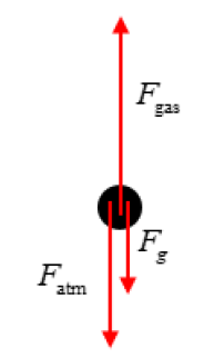
Because the piston is at rest, these forces balance.
B.
For a monatomic ideal gas,
\( U = \dfrac{3}{2}nRT \)
and from the ideal gas law,
\( PV = nRT \)
so
\( U = \dfrac{3}{2}PV \)
Now find the gas pressure using force balance on the piston:
Upward force from the gas: \( PA \)
Downward forces: \( P_{\mathrm{atm}}A + Mg \)
Since the piston is at rest,
\( PA – P_{\mathrm{atm}}A – Mg = 0 \)
\( P = P_{\mathrm{atm}} + \dfrac{Mg}{A} \)
Therefore,
\( U = \dfrac{3}{2}PV_0 \)
\( \boxed{U = \dfrac{3}{2}\left(P_{\mathrm{atm}} + \dfrac{Mg}{A}\right)V_0} \)
This works nicely because the gas is ideal and monatomic, so internal energy depends only on temperature, and \( PV \) gives the same result through the ideal gas law.
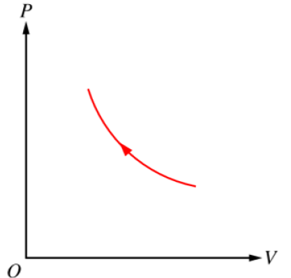
C.
Because the container is thermally conducting and the water bath remains at constant temperature, the process is approximately isothermal.
When the extra block is slowly added, the external pressure on the gas increases, so the gas is compressed. For an isothermal compression, \( PV = \text{constant} \), so the \( P\text{-}V \) curve is a hyperbola.
The process moves from a point at lower pressure and larger volume to a point at higher pressure and smaller volume, so the arrow points up and to the left along a concave-up curve.
D.
\( \boxed{T_{\mathrm{new}} > T_0} \)
With the extra block still on the piston, the gas must support a larger downward force than it did initially. Therefore, at equilibrium the gas pressure is larger than before.
In part \( \mathrm{B} \), the initial pressure was \( P_{\mathrm{atm}} + \dfrac{Mg}{A} \). With an added block of the same mass \( M \), the final equilibrium pressure at volume \( V_0 \) is
\( P_{\mathrm{final}} = P_{\mathrm{atm}} + \dfrac{2Mg}{A} \)
Since the gas ends at the same volume \( V_0 \) but at a larger pressure, the ideal gas law implies a larger temperature:
\( PV = nRT \)
With \( n \) constant and \( V \) unchanged, larger \( P \) means larger \( T \). Therefore, \( T_{\mathrm{new}} > T_0 \).
This is also consistent with the \( P\text{-}V \) picture in part \( \mathrm{C} \): to return to the original volume while supporting the added block, the gas must end at a higher pressure than it had initially.
Question 3
A. Describe a procedure for collecting data that would allow the student to determine the expected time constant \( \tau \). In your description, include the measurements to be made. Include any steps necessary to reduce experimental uncertainty.
| Table \( 1 \) | |
|---|---|
| \( |\Delta V| \) \( (\mathrm{V}) \) | \( q \) \( (\times 10^{-10}\ \mathrm{C}) \) |
| \( 3.0 \) | \( 2.4 \) |
| \( 5.0 \) | \( 4.2 \) |
| \( 7.2 \) | \( 5.6 \) |
| \( 8.0 \) | \( 6.6 \) |
| \( 10.0 \) | \( 8.0 \) |
• Clearly label the axes, including units as appropriate.
• Plot the points you recorded in Table \( 2 \).

Most-appropriate topic codes (AP Physics 2):
• Topic \( 11.3 \) — Resistance, Resistivity, and Ohm’s Law (Part \( \mathrm{A} \), Part \( \mathrm{B} \))
• Topic \( 11.8 \) — Resistor-Capacitor \( (\mathrm{RC}) \) Circuits (Part \( \mathrm{A} \), Part \( \mathrm{B} \))
▶️ Answer/Explanation
A.
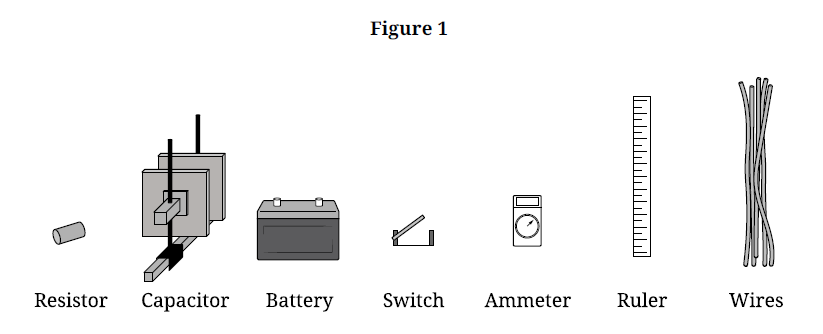
A valid procedure is to determine the resistance \( R \) of the resistor from the battery emf and the initial current, and to determine the capacitance \( C \) from the geometry of the air-filled parallel-plate capacitor.
First, measure the side length \( \ell \) of one square capacitor plate with the ruler. Then measure the plate separation \( d \) with the ruler. Since the plates are square, the plate area is \( A = \ell^2 \).
Next, connect the battery, resistor, ammeter, switch, and capacitor in series. Close the switch and record the initial current \( I_0 \) shown by the ammeter immediately after the circuit is completed.
Because the capacitor is initially uncharged, it behaves like a wire at that instant, so the initial current can be used to determine the resistor’s resistance. Then open the switch, fully discharge the capacitor, and repeat the current measurement several times. Average the values of \( I_0 \) to reduce random uncertainty.
Repeating the dimension measurements and averaging them also improves the estimate of \( \ell \) and \( d \).
B.
The expected time constant is
\( \tau = R_{\mathrm{eq}}C_{\mathrm{eq}} \)
Since there is only one resistor and one capacitor in series,
\( \tau = RC \)
Determine the resistance from the initial current:
\( R = \dfrac{\mathcal{E}}{I_0} \)
where \( \mathcal{E} \) is the known battery emf.
Determine the capacitance from the parallel-plate formula:
\( C = \kappa \epsilon_0 \dfrac{A}{d} \)
Since the dielectric constant of air is \( \kappa = 1 \),
\( C = \epsilon_0 \dfrac{\ell^2}{d} \)
Therefore,
\( \tau = \left(\dfrac{\mathcal{E}}{I_0}\right)\left(\epsilon_0 \dfrac{\ell^2}{d}\right) \)
\( \boxed{\tau = \dfrac{\epsilon_0 \mathcal{E}\,\ell^2}{I_0 d}} \)
So once \( \ell \), \( d \), and \( I_0 \) are measured, the student can calculate the expected time constant.
C(i)
One correct choice is:
Vertical axis: \( q \) \( (\times 10^{-10}\ \mathrm{C}) \)
Horizontal axis: \( |\Delta V| \) \( (\mathrm{V}) \)
because \( q = C|\Delta V| \), which is a linear relationship whose slope is \( C \).
C(ii)
A correct plotting table is:
| Table \( 2 \) | |
|---|---|
| \( |\Delta V| \) \( (\mathrm{V}) \) | \( q \) \( (\times 10^{-10}\ \mathrm{C}) \) |
| \( 3.0 \) | \( 2.4 \) |
| \( 5.0 \) | \( 4.2 \) |
| \( 7.2 \) | \( 5.6 \) |
| \( 8.0 \) | \( 6.6 \) |
| \( 10.0 \) | \( 8.0 \) |
A correct graph is shown below.
C(iii)
Draw a straight best-fit line through the plotted points, since the data are approximately linear.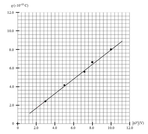
D.
Using \( q = C|\Delta V| \), the slope of a graph of \( q \) versus \( |\Delta V| \) is the capacitance \( C \).
Using two convenient points on the best-fit line, for example about \( (3.0,\ 2.4) \) and \( (10.0,\ 8.0) \) in the plotted units:
\( \text{slope} = \dfrac{\Delta q}{\Delta |\Delta V|} = \dfrac{(8.0-2.4)\times 10^{-10}\ \mathrm{C}}{10.0-3.0\ \mathrm{V}} \)
\( \text{slope} = \dfrac{5.6\times 10^{-10}}{7.0}\ \dfrac{\mathrm{C}}{\mathrm{V}} \approx 8.0\times 10^{-11}\ \mathrm{F} \)
Therefore,
\( \boxed{C \approx 8\times 10^{-11}\ \mathrm{F}} \)
This is reasonable because all the data points lie close to a single straight line, indicating an approximately constant capacitance.
Question 4
Most-appropriate topic codes (AP Physics 2):
▶️ Answer/Explanation
A.
The student’s claim is correct.
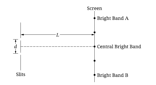
Violet light has a shorter wavelength than red light. For a bright fringe, the path-length difference between light from the two slits must equal an integer multiple of the wavelength.
Since Band \( A \) corresponds to a fixed bright-fringe order, the required path-length difference for violet light is smaller than for red light.
A smaller path-length difference means the point on the screen must be closer to the central bright band. Therefore, the distance from Band \( A \) to the central bright band is smaller for violet light.
B.
For double-slit interference, constructive interference occurs when
\( d\sin\theta = m\lambda \)
Because there are three bright bands between \( A \) and \( B \), including the central bright band, bands \( A \) and \( B \) must be the second-order bright fringes:
\( m = 2 \)
For small angles,
\( \sin\theta \approx \tan\theta \approx \dfrac{y}{L} \)
so
\( d\left(\dfrac{y}{L}\right)=m\lambda \)
\( y=\dfrac{m\lambda L}{d} \)
For Band \( A \),
\( y_A=\dfrac{2\lambda L}{d} \)
Band \( B \) is the same distance below the center, so the distance between \( A \) and \( B \) is
\( \Delta y = 2y_A = 2\left(\dfrac{2\lambda L}{d}\right) \)
\( \Delta y = \dfrac{4\lambda L}{d} \)
Using \( \lambda=\dfrac{c}{f} \),
\( \boxed{\Delta y = \dfrac{4cL}{fd}} \)
C.
Yes, the expression from part \( \mathrm{B} \) is consistent with the answer in part \( \mathrm{A} \).
Since \( \Delta y = \dfrac{4cL}{fd} \), the spacing between the two second-order bright bands is inversely proportional to frequency.
Violet light has a greater frequency than red light, so \( \Delta y \) is smaller for violet light. That means each bright band is closer to the central bright band, which matches the claim in part \( \mathrm{A} \).