Question
Ten cells, each of electromotive force (e.m.f.) 1.5 V, are connected together, as shown.

What is the combined e.m.f. between terminals X and Y?
A \(8\)V B \(9\)V C \(12\) V D \(15\)V
Answer/Explanation
Ans:
Question
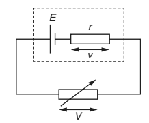
A cell of electromotive force (e.m.f.) E and internal resistance r is connected to a variable resistor, as shown.

The resistance of the variable resistor is gradually increased from r to 3r.
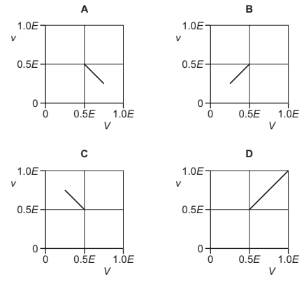
Which graph shows the variation of the potential difference (p.d.) v across the internal resistance with the p.d. V across the variable resistor?

Answer/Explanation
Ans:
Question
What is the circuit symbol for an oscilloscope?

Answer/Explanation
Ans :
Question
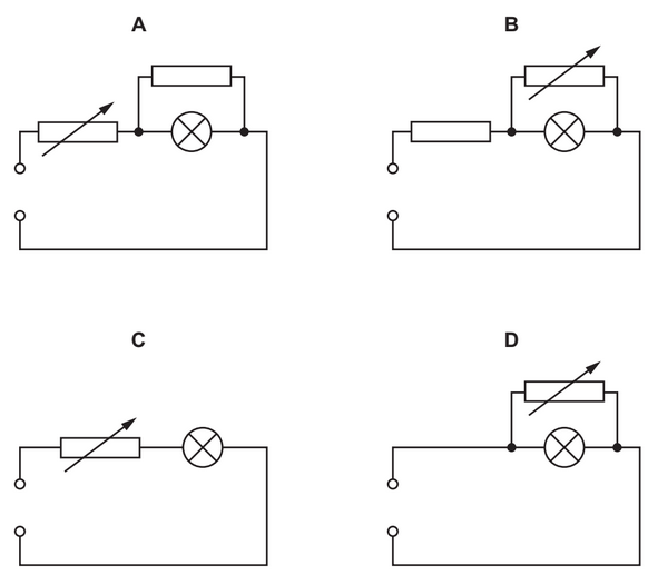
In the circuits shown, the power supply has an electromotive force (e.m.f.) greater than the
normal operating voltage of the lamp. The internal resistance of the power supply is negligible.
The resistance of the variable resistor is adjusted from zero to its maximum value.
In which circuit could the voltage across the lamp change from zero to its normal operating
voltage and not exceed its normal operating voltage?
Answer/Explanation
Question
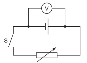
A cell that has internal resistance is connected to a switch S and a variable resistor. A voltmeter
is connected between the terminals of the cell, as shown.

When switch S is open, the voltmeter reads 1.5V. The switch is then closed and the variable
resistor is adjusted to have a resistance of 4.0Ω. The voltmeter now reads 0.75V.
What is the internal resistance of the cell?
A 1.0Ω B 2.0Ω C 4.0Ω D 8.0Ω
Answer/Explanation
Ans
