Question
(a) State Kirchhoff’s second law.
…………………………………………………………………………………………………………………………………
…………………………………………………………………………………………………………………………………
……………………………………………………………………………………………………………………………
(b) A battery has electromotive force (e.m.f.) 4.0V and internal resistance 0.35Ω. The battery is
connected to a uniform resistance wire XY and a fixed resistor of resistance R, as shown in
Fig. 5.1.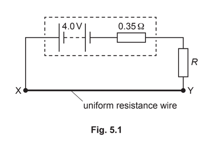
Wire XY has resistance 0.90Ω. The potential difference across wire XY is 1.8V.
Calculate:
(i) the current in wire XY
current = ……………………………………………… A [1]
(ii) the number of free electrons that pass a point in the battery in a time of 45s
number = …………………………………………………
(iii) resistance R.
R = …………………………………………….. Ω
(c) A cell of e.m.f. 1.2V is connected to the circuit in (b), as shown in Fig. 5.2.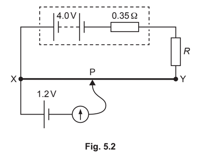
The connection P is moved along the wire XY. The galvanometer reading is zero when distance XP is 0.30m.
(i) Calculate the total length L of wire XY.
L = …………………………………………….. m [2]
(ii) The fixed resistor is replaced by a different fixed resistor of resistance greater than R.
State and explain the change, if any, that must be made to the position of P on wire XY so that the galvanometer reading is zero.
………………………………………………………………………………………………………………………….
………………………………………………………………………………………………………………………….
Answer/Explanation
Ans:
(a) sum of e.m.f.(s) = sum of p.d.(s)
or
(algebraic) sum of e.m.f.(s) and p.d.(s) is zero
around a loop/around a closed circuit
(b)(i) I = 1.8 / 0.90= 2.0A
(b)(ii) Q =It
number \(= (2.0\times 45) / 1.60\times 10^{–19}= 5.6 \times 10^{20}\)
(b)(iii) 4.0 = 1.8 + [2.0× (0.35 +R)]
or
4.0 = 2.0× (0.90 + 0.35 +R)
R = 0.75Ω
(c)(i) 1.2 / 1.8 = 0.30 / L
L = 0.45 m
(c)(ii) p.d. across XY decreases/p.d. across XP decreases
(so) P is moved towards Y/away from X/to the right
Question
(a) Metal wire is used to connect a power supply to a lamp. The wire has a total resistance of 3.4Ω and the metal has a resistivity of \(2.6 × 10^{–8}Ωm\). The total length of the wire is 59m.
(i) Show that the wire has a cross-sectional area of \(4.5 × 10^{–7}m^2\).
(ii) The potential difference across the total length of wire is 1.8V.
Calculate the current in the wire.
current = ………………………………………………
(iii) The number density of the free electrons in the wire is \(6.1×10^{28}m^{–3}\).
Calculate the average drift speed of the free electrons in the wire.
average drift speed = ………………………………………… \(ms^{–1}\)
(b) A different wire carries a current. This wire has a part that is thinner than the rest of the wire, as
shown in Fig. 5.1.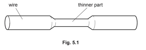
(i) State and explain qualitatively how the average drift speed of the free electrons in the
thinner part compares with that in the rest of the wire.
(ii) State and explain whether the power dissipated in the thinner part is the same, less or
more than the power dissipated in an equal length of the rest of the wire.
(c) Three resistors have resistances of 180Ω, 90Ω and 30Ω.
(i) Sketch a diagram showing how two of these three resistors may be connected together
to give a combined resistance of 60Ω between the terminals shown.
Ensure you label the values of the resistances in your diagram.
(ii) A potential divider circuit is produced by connecting the three resistors to a battery of
electromotive force (e.m.f.) 12V and negligible internal resistance. The potential divider
circuit provides an output potential difference \(V_{OUT}\) of 8.0V.
Fig. 5.2 shows the circuit diagram.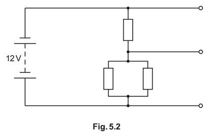
On Fig. 5.2, label the resistances of all three resistors and the potential difference \(V_{OUT}\).
Answer/Explanation
Answer:
(a) (i) R = ρL / A
\(A = (2.6 × 10^{–8} × 59) / 3.4 = 4.5 × 10^{–7} m^2\)
(ii) I = 1.8 / 3.4
= 0.53 A
(iii) I = Anvq
\(v = 0.53 / (4.5 × 10^{–7} × 6.1 × 10^{28} × 1.60 × 10^{–19})\)
\(= 1.2 × 10^{–4} m s^{–1}\)
(b) (i) (cross-sectional) area/A is less
(I, n, e the same so) average drift speed is greater
(ii) (area is less so) more resistance/R
(I is the same, so) more power/P
or
(P = I2ρL / A so) P ∝ 1 / A(A is less so) more P
(c)(i) 180 Ω and 90 Ω resistors shown connected in parallel
(ii) resistors connected in parallel labelled as 180 Ω and 90 Ω and the other resistor labelled as 30 Ω
\(V_{OUT}\) or 8.0 V labelled across the two resistors in parallel