Question
A small solenoid of area of cross section \(1.6 \times 10^{–3} m^{2}\) is placed inside a larger solenoid of area of cross-section \(6.4 \times 10^{–3}m^{2}\), as shown in Fig. 6.1.
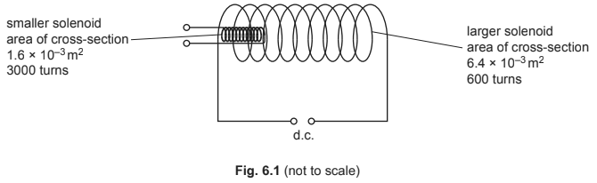
The larger solenoid has \(600\) turns and is attached to a d.c. power supply to create a magnetic field.
The smaller solenoid has \(3000\) turns.
(a) Compare the magnetic flux in the two solenoids.
(b) Compare the magnetic flux linkage in the two solenoids.
(c) (i) State Lenz’s law of electromagnetic induction.
(ii) The terminals of the smaller solenoid are connected together. The smaller solenoid is then removed from inside the larger solenoid.
With reference to magnetic fields, explain why a force is needed to remove the smaller solenoid.
Answer/Explanation
Ans:
(a) less in smaller solenoid
(b) greater in smaller solenoid
(c) (i) direction of (induced) e.m.f.
such as to (produce effects that) oppose the change that caused it
(ii) change of flux (linkage) in smaller solenoid induces e.m.f. in smaller solenoid
(induced) current in smaller solenoid causes field around it
Question
(a) Define magnetic flux linkage. [2]
(b) A solenoid of diameter 6.0cm and 540 turns is placed in a uniform magnetic field as shown in Fig. 9.1.
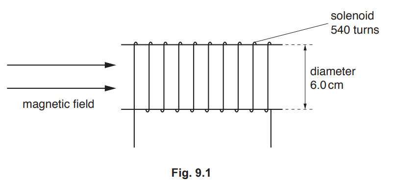
The variation with time t of the magnetic flux density is shown in Fig. 9.2.
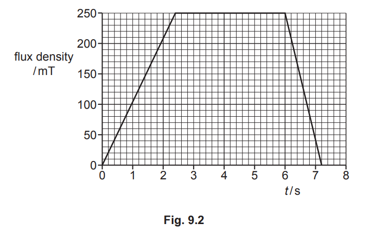
Calculate the maximum magnitude of the induced electromotive force (e.m.f.) in the solenoid.
e.m.f. = ……………………………………………… V [3]
(c) A thin copper sheet X is supported on a rigid rod so that it hangs between the poles of a
magnet as shown in Fig. 9.3.
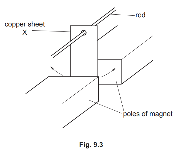
Sheet X is displaced to one side and then released so that it oscillates. A motion sensor is
used to record the displacement of X.
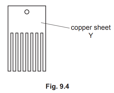
A second thin copper sheet Y replaces sheet X. Sheet Y has the same overall dimensions as
X but is cut into the shape shown in Fig. 9.4.
The motion sensor is again used to record the displacement.
The graph in Fig. 9.5 shows the variation with time t of the displacement s of each copper
sheet.
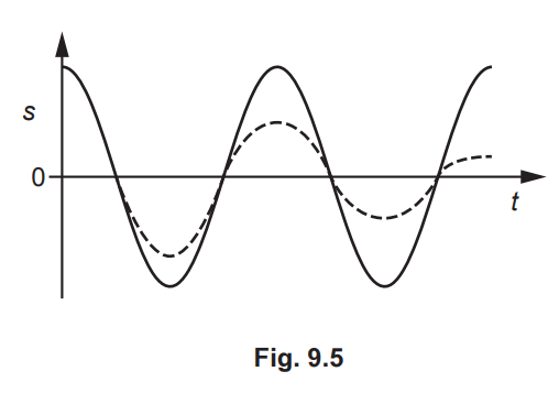
(i) State the name of the phenomenon illustrated by the gradual reduction in the amplitude
of the dashed line. [1]
(ii) Deduce which copper sheet is represented by the dashed line. Explain your answer
using the principles of electromagnetic induction. [4]
[Total: 10]
Answer/Explanation
Ans
(a) (magnetic) flux density × area × number of turns
area is perpendicular to (magnetic) field
(b) use of t = 1.2 s
\(\varepsilon=\frac{\Delta BAN}{\Delta T}\)
\(=\frac{0.250\times \pi \times 0.030^{2}\times 540}{1.2}\)
= 0.32V
(c) (i) light damping
(c) (ii) sheet cuts (magnetic) flux and causes induced emf
(induced) emf causes (eddy) currents (in sheet)
either currents (in sheet) cause resistive force
or currents (in sheet) dissipate energy