Recall and Use of Standard Circuit Symbols
Circuit symbols are standardized graphical representations of electrical components used in circuit diagrams. They make circuit drawings clear, simple, and universally understandable.
Purpose:
- To simplify complex circuits.
- To communicate circuit designs universally and unambiguously.
To allow easy interpretation and analysis of circuit behavior.
Common Circuit Symbols (as per A Level Physics / Section 6)
| Component | Symbol | Function / Description |
|---|---|---|
| Cell | 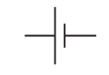 | Provides electrical energy; single unit of a battery. |
| Battery | 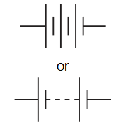 | Supplies energy to the circuit by maintaining a potential difference. |
| Power Supply (DC / AC) |
| Provides direct or alternating current to a circuit. |
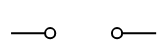
| Switch (open / closed) | 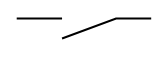 | Controls whether current flows in a circuit. |
| Resistor | 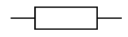 | Limits or controls current flow. |
| Variable Resistor (Rheostat) |  | Allows resistance (and current) to be adjusted manually. |
| Potentiometer |  | Divides voltage; used to vary potential difference. |
| Thermistor |  | Resistance decreases as temperature increases (NTC type). |
| Light-dependent Resistor (LDR) | 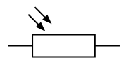 | Resistance decreases as light intensity increases. |
| Filament Lamp / Bulb | 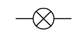 | Converts electrical energy to light and heat. |
| Heater | 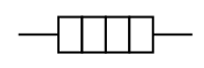 | Converts electrical energy into heat energy. |
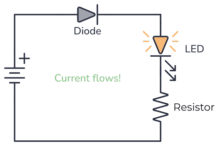
| Diode | 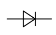 | Allows current to flow in only one direction. |
| Light Emitting Diode (LED) | 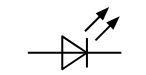 | Emits light when current flows in forward direction. |
| Capacitor | 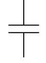 | Stores electric charge and energy in an electric field. |
| Ammeter | 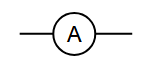 | Measures current; connected in series. |
| Voltmeter | 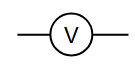 | Measures potential difference; connected in parallel. |
| Galvanometer | 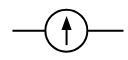 | Detects and measures small electric currents. |
| Fuse |  | Protects circuit by melting when current exceeds safe value. |
| Earth / Ground |  | Provides a zero-potential reference point. |
| Motor | 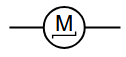 | Converts electrical energy into mechanical rotation. |
| Generator | 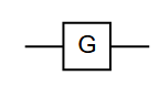 | Converts mechanical energy into electrical energy. |
| Electric Bell |  | Produces ringing sound when current passes through it. |
| Buzzer |  | Emits buzzing sound; used for alarms or indicators. |
| Microphone | Converts sound energy into electrical signals. | |
| Loudspeaker | 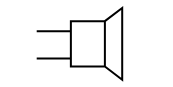 | Converts electrical signals into sound energy. |
| Oscilloscope | 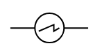 | Displays voltage variation with time on a screen. |
| Junction of Conductors | 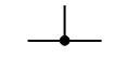 | Indicates a joining point for conductors. |
Each symbol represents an internationally recognized electrical component, ensuring clear and standardized circuit diagrams across engineering and physics contexts.
Conclusion: Recognizing and correctly using circuit symbols is essential for drawing and interpreting circuit diagrams accurately in both theoretical and practical work.
Example
Draw and label a circuit that includes a cell, a switch, a resistor, an ammeter, and a voltmeter to measure the voltage across the resistor.
▶️ Answer / Explanation
- Step 1: Use a single cell symbol (long and short lines) for the power supply.
- Step 2: Place a switch in series with the cell to control the circuit.
- Step 3: Connect a resistor symbol (zigzag line) after the switch — this is the load.
- Step 4: Place an ammeter (circle with “A”) in series to measure current.
- Step 5: Connect a voltmeter (circle with “V”) in parallel across the resistor to measure potential difference.
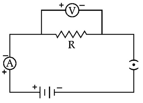
Interpretation: The circuit measures both the current and the voltage across the resistor. These readings can be used to calculate resistance using \( \mathrm{R = \dfrac{V}{I}}. \)
Key Point: Correct use of circuit symbols ensures the circuit diagram is easily understood and follows international electrical standards.
Drawing and Interpreting Circuit Diagrams
A circuit diagram is a simplified visual representation of an electrical circuit using standard circuit symbols to show how components are connected.
Guidelines for Drawing Circuit Diagrams:
- Use only standard circuit symbols.
- Draw with straight horizontal and vertical lines; avoid curves or angles.
- Label all components clearly (e.g., resistor values, cell voltages).
- Show the direction of conventional current (from + to – terminal).
- Ensure the layout is neat and logically arranged for easy reading.
Common Circuit Examples and Interpretations:
| Type of Circuit | Diagram Description | Interpretation |
|---|---|---|
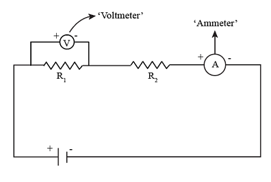
| Simple Circuit with Ammeter and Voltmeter |
Battery → switch → resistor → ammeter in series → voltmeter connected across resistor | Used to measure the current through and potential difference across a resistor. The voltmeter is in parallel; ammeter is in series. |
| Series Circuit |
Multiple resistors connected end-to-end with one current path | Current is the same through all components, but potential difference divides among them. |
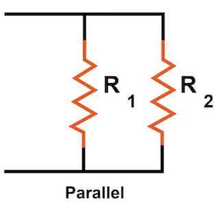
| Parallel Circuit |
Resistors connected side by side, both ends connected to the same two points | Potential difference across each branch is the same; current splits between branches. |
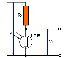
| LDR in Potential Divider Circuit |
Two resistors (one is an LDR) connected in series across a voltage supply; output voltage taken across one resistor | As light intensity increases, LDR resistance decreases → voltage across LDR decreases → output voltage across other resistor increases. |
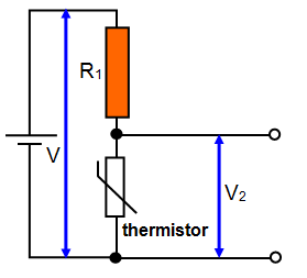
| Thermistor in Potential Divider Circuit |
Two resistors (one is a thermistor) connected across a voltage supply; output voltage taken across one resistor | As temperature increases, thermistor resistance decreases → voltage across thermistor decreases → output voltage across other resistor increases. |
| Diode Circuit |
Battery → resistor → diode → ammeter (series) | Current flows only when diode is forward-biased (anode to positive terminal). In reverse bias, current is negligible. |

Interpreting Circuit Diagrams:
- Identify power source(s) — determine polarity or type (DC or AC).
- Trace the current path — noting all series and parallel branches.
- Locate measurement devices (Ammeter in series, Voltmeter in parallel).
- Identify control devices like switches, variable resistors, or sensors (LDRs, thermistors).
- Recognize components that restrict current flow (resistors, diodes) or change it with conditions (LDR, thermistor).
Example
Draw and describe a circuit to measure the resistance of a resistor using an ammeter and a voltmeter.
▶️ Answer / Explanation
- Connect a resistor in series with an ammeter and a variable resistor to a battery.
- Connect a voltmeter across the resistor to measure potential difference.
- Use the readings to calculate resistance using \( \mathrm{R = \dfrac{V}{I}}. \)
- Plot \( \mathrm{V\text{-}I} \) graph; the gradient gives resistance.

Purpose: Verify Ohm’s Law using measured current and voltage values.
Example
Interpret a circuit containing a thermistor in a potential divider controlling a cooling fan.
▶️ Answer / Explanation
At low temperatures, the thermistor’s resistance is high → high voltage across it → low voltage across the fan → fan off. At high temperatures, thermistor resistance decreases → less voltage across thermistor → more voltage across the fan → fan turns on automatically.
Conclusion: The circuit acts as an automatic temperature control system using a thermistor as a sensor.
Definition and Use of Electromotive Force (e.m.f.)
The electromotive force (e.m.f.) of a source is defined as the energy transferred per unit charge from the source’s chemical, mechanical, or other energy forms into electrical energy, as it drives charge around a complete circuit.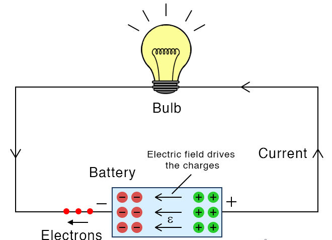
\( \mathrm{\varepsilon = \dfrac{W}{Q}} \)
Where:
- \( \mathrm{\varepsilon} \): electromotive force (volts, V)
- \( \mathrm{W} \): electrical energy supplied by the source (joules, J)
- \( \mathrm{Q} \): charge moved (coulombs, C)
Explanation:
- When one coulomb of charge passes through the source, \( \mathrm{\varepsilon} \) joules of energy are provided to the circuit by the source.
- The e.m.f. represents the total energy conversion per unit charge by the source — e.g., chemical → electrical energy in a cell.
- It is the driving voltage that pushes charge around the circuit, even when current flows through internal resistance.
E.m.f. measures the total energy supplied per unit charge by the source — it is the “energy per coulomb” given to the circuit.
Example
A battery supplies \( \mathrm{12 \ J} \) of energy to move \( \mathrm{2 \ C} \) of charge through a circuit. Find the e.m.f. of the battery.
▶️ Answer / Explanation
Using \( \mathrm{\varepsilon = \dfrac{W}{Q}} \):
\( \mathrm{\varepsilon = \dfrac{12}{2} = 6.0 \ V.} \)
Hence, the e.m.f. of the battery is 6.0 V.
Example
A 9 V battery drives a current of \( \mathrm{2.0 \ A} \) for \( \mathrm{5.0 \ minutes.} \) Find the total electrical energy transferred to the circuit.
▶️ Answer / Explanation
Charge moved: \( \mathrm{Q = It = 2.0 \times (5.0 \times 60) = 600 \ C.} \)
Energy transferred: \( \mathrm{W = \varepsilon Q = 9 \times 600 = 5400 \ J.} \)
Therefore, 5400 J of energy are supplied to the circuit by the battery.
Distinguishing Between e.m.f. and Potential Difference (p.d.)

| Quantity | Definition | Energy Consideration | Where It Occurs |
|---|---|---|---|
| Electromotive force (e.m.f.) | Energy supplied per unit charge by the source to drive charge around a complete circuit. | Represents energy gain per coulomb by the charge as it passes through the source (e.g., battery). | Occurs in the power source — e.g., within a cell, generator, or battery. |
| Potential difference (p.d.) | Energy transferred per unit charge by the charge to a component as it moves through it. | Represents energy loss per coulomb by the charge when doing work (e.g., heating a resistor). | Occurs across circuit components (resistors, lamps, etc.) when current flows. |
Mathematically:
- E.m.f. of a source: \( \mathrm{\varepsilon = \dfrac{W_{\text{supplied}}}{Q}} \)
- Potential difference across a component: \( \mathrm{V = \dfrac{W_{\text{used}}}{Q}} \)
Energy Flow Summary:
Source: provides energy → Charges: carry energy → Components: use energy
E.m.f. vs Potential Difference
| Aspect | Electromotive Force (e.m.f.) | Potential Difference (p.d.) |
|---|---|---|
| Definition | Energy supplied per coulomb by the source. | Energy used per coulomb by a component. |
| Equation | \( \mathrm{\varepsilon = \dfrac{W_{\text{supplied}}}{Q}} \) | \( \mathrm{V = \dfrac{W_{\text{used}}}{Q}} \) |
| Occurs in | Energy sources (battery, generator). | Energy-consuming components (resistors, lamps). |
| Energy direction | Energy gained by charges. | Energy lost by charges. |
| Measurement | Measured across source with open circuit (no current). | Measured across components while current flows. |
Example
Explain why the e.m.f. of a cell is slightly greater than the potential difference measured across its terminals when current flows.
▶️ Answer / Explanation
When current flows, some energy is lost as heat due to the internal resistance of the cell. Therefore, the terminal potential difference is slightly less than the total e.m.f. of the cell.
\( \mathrm{\varepsilon = V + Ir} \)
where \( \mathrm{r} \) is the internal resistance and \( \mathrm{I} \) is the current.
Hence, the e.m.f. is the total energy per coulomb supplied, while the terminal p.d. is the useful energy per coulomb delivered to the external circuit.
Example
A cell of e.m.f. \( \mathrm{1.5 \ V} \) drives a current of \( \mathrm{0.3 \ A} \) through a circuit with an internal resistance of \( \mathrm{1.0 \ \Omega.} \) Find the terminal potential difference.
▶️ Answer / Explanation
Using \( \mathrm{\varepsilon = V + Ir} \):
\( \mathrm{V = \varepsilon – Ir = 1.5 – (0.3)(1.0) = 1.2 \ V.} \)
Hence, the terminal p.d. is 1.2 V.
Interpretation: Each coulomb of charge gains 1.5 J from the cell, but only 1.2 J is delivered to the external circuit — 0.3 J is lost as heat inside the cell.
Effect of Internal Resistance on Terminal Potential Difference
Internal Resistance:
The internal resistance of a source (such as a battery or cell) is the resistance to current flow within the source itself. It is caused by the materials and chemicals inside the cell that oppose the motion of charge carriers.
Symbol: \( \mathrm{r} \) (measured in ohms, \( \mathrm{\Omega} \))
Model of a Real Source:
- A real source of e.m.f. can be represented as an ideal e.m.f. (ε) in series with an internal resistance (r).
- When a current \( \mathrm{I} \) flows, some of the energy supplied by the source is lost as heat in its internal resistance.
Key Equation:
\( \mathrm{\varepsilon = V + Ir} \)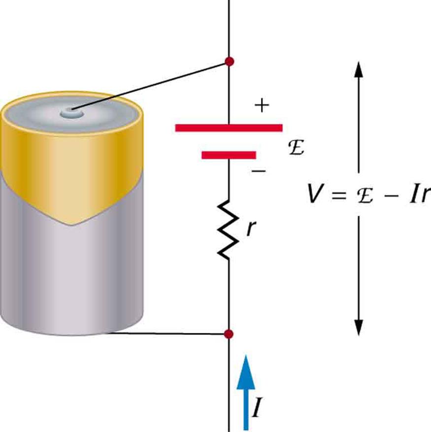
Where:
- \( \mathrm{\varepsilon} \): e.m.f. of the source (V)
- \( \mathrm{V} \): terminal potential difference (V) — voltage across the external circuit
- \( \mathrm{I} \): current (A)
- \( \mathrm{r} \): internal resistance (Ω)
Therefore:
\( \mathrm{V = \varepsilon – Ir} \)
Explanation of the Equation:
- When current flows, a part of the total e.m.f. (\( \mathrm{Ir} \)) is “lost” inside the source as heat.
- The remaining energy per coulomb (\( \mathrm{V} \)) is available to the external circuit.
- As current increases, \( \mathrm{Ir} \) increases — therefore, the terminal potential difference decreases.
The internal resistance of a source causes the terminal potential difference to be less than the e.m.f. whenever current flows. The greater the current, the larger the voltage drop inside the source.
Graphical Representation:
If a graph of \( \mathrm{V} \) (terminal p.d.) vs \( \mathrm{I} \) (current) is plotted, it is a straight line with a negative gradient.
\( \mathrm{V = \varepsilon – Ir} \quad \Rightarrow \quad \text{Gradient} = -r, \ \text{Intercept} = \varepsilon \)
Interpretation:
- At \( \mathrm{I = 0} \) (no current), \( \mathrm{V = \varepsilon} \) → the terminal p.d. equals the e.m.f. (open circuit).
- As \( \mathrm{I} \) increases, \( \mathrm{V} \) decreases linearly due to energy loss inside the source.
Energy Consideration:
The total energy per unit charge supplied by the source (\( \mathrm{\varepsilon} \)) divides into two parts:
- \( \mathrm{V} \): energy per coulomb delivered to the external circuit (useful work).
- \( \mathrm{Ir} \): energy per coulomb dissipated as heat inside the source (lost energy).
\( \mathrm{\varepsilon = V + Ir} \)
Key Energy Flow :
Total energy supplied = Useful energy + Lost energy
Practical Implications:
- Devices connected to a source with high internal resistance receive less voltage under load.
- High internal resistance reduces efficiency in power delivery (e.g., old batteries deliver less power).
- To minimize energy loss, good power supplies are designed with very low internal resistance.
Example
A battery has an e.m.f. of \( \mathrm{12.0 \ V} \) and an internal resistance of \( \mathrm{2.0 \ \Omega.} \) It delivers a current of \( \mathrm{1.5 \ A.} \) Find the terminal potential difference.
▶️ Answer / Explanation
Using \( \mathrm{V = \varepsilon – Ir} \):
\( \mathrm{V = 12.0 – (1.5)(2.0) = 12.0 – 3.0 = 9.0 \ V.} \)
Therefore, the terminal potential difference is 9.0 V.
Interpretation: 3.0 V of the source’s e.m.f. is lost internally as heat, leaving 9.0 V to power the external circuit.
Example
A 6.0 V battery with internal resistance \( \mathrm{0.5 \ \Omega} \) is connected to two different loads: (a) \( \mathrm{5.5 \ \Omega} \), and (b) \( \mathrm{1.0 \ \Omega.} \) Calculate the terminal voltage in both cases.
▶️ Answer / Explanation
(a) Total resistance \( \mathrm{R_T = 5.5 + 0.5 = 6.0 \ \Omega.} \)
\( \mathrm{I = \dfrac{\varepsilon}{R_T} = \dfrac{6.0}{6.0} = 1.0 \ A.} \)
\( \mathrm{V = \varepsilon – Ir = 6.0 – (1.0)(0.5) = 5.5 \ V.} \)
(b) Total resistance \( \mathrm{R_T = 1.0 + 0.5 = 1.5 \ \Omega.} \)
\( \mathrm{I = \dfrac{6.0}{1.5} = 4.0 \ A.} \)
\( \mathrm{V = \varepsilon – Ir = 6.0 – (4.0)(0.5) = 4.0 \ V.} \)
Interpretation: When the external resistance is smaller, current increases, and the voltage drop inside the battery increases. Thus, terminal voltage decreases more at higher currents.