Principle of a Potential Divider Circuit
A potential divider is a circuit that divides a supply voltage into smaller, desired portions using two or more resistors (or other components such as LDRs or thermistors) connected in series across a voltage source.
Basic Circuit Diagram Description: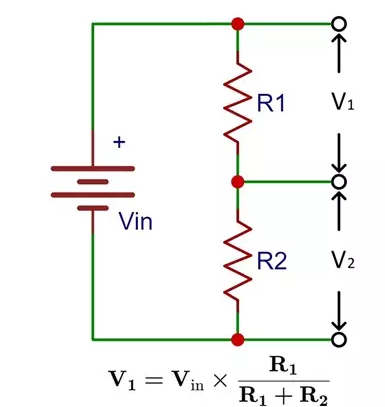
- Two resistors, \( \mathrm{R_1} \) and \( \mathrm{R_2} \), are connected in series across a supply voltage \( \mathrm{V} \).
- The same current \( \mathrm{I} \) flows through both resistors (since they are in series).
- The voltage across each resistor depends on its resistance value.
Formula Derivation:
\( \mathrm{V = V_1 + V_2} \)
From Ohm’s law, \( \mathrm{V_1 = IR_1} \) and \( \mathrm{V_2 = IR_2} \). Also, \( \mathrm{I = \dfrac{V}{R_1 + R_2}} \).
Substitute for \( \mathrm{I} \):
\( \mathrm{V_1 = \dfrac{R_1}{R_1 + R_2} \, V} \quad \text{and} \quad \mathrm{V_2 = \dfrac{R_2}{R_1 + R_2} \, V} \)
Hence, each resistor receives a fraction of the total voltage proportional to its resistance.
A potential divider circuit provides an output voltage that can be controlled or varied by changing one of the resistances, without changing the total supply voltage.
Applications of Potential Divider Circuits:
- Voltage control: To supply a fixed or variable fraction of voltage to a component (e.g., a transistor base or amplifier input).
- Sensor circuits: Using a thermistor or LDR as one resistor to vary output voltage with temperature or light intensity.
- Volume control: In radios or audio devices using a variable resistor (potentiometer).
Example
A potential divider has two resistors, \( \mathrm{R_1 = 2.0 \, k\Omega} \) and \( \mathrm{R_2 = 3.0 \, k\Omega} \), connected across a \( \mathrm{10 \, V} \) supply. Find the voltage across \( \mathrm{R_2} \).
▶️ Answer / Explanation
Using \( \mathrm{V_2 = \dfrac{R_2}{R_1 + R_2} \, V} \):
\( \mathrm{V_2 = \dfrac{3.0}{2.0 + 3.0} \times 10 = \dfrac{3}{5} \times 10 = 6.0 \, V.} \)
Hence, the output voltage across \( \mathrm{R_2} \) is 6.0 V.
Example
A thermistor (whose resistance decreases with increasing temperature) replaces \( \mathrm{R_2} \) in a potential divider. Explain how the output voltage across the thermistor changes as temperature increases.
▶️ Answer / Explanation
As temperature increases, the thermistor’s resistance \( \mathrm{R_2} \) decreases. From \( \mathrm{V_2 = \dfrac{R_2}{R_1 + R_2} \, V} \), when \( \mathrm{R_2} \) decreases, the fraction \( \mathrm{\dfrac{R_2}{R_1 + R_2}} \) becomes smaller, so the output voltage \( \mathrm{V_2} \) decreases.
Hence, higher temperature → lower output voltage.
Principle of the Potentiometer — Comparing Potential Differences
A potentiometer is an instrument used to measure or compare potential differences (p.d.) by balancing them against a known voltage from a uniform resistance wire supplied by a stable source.
Basic Principle: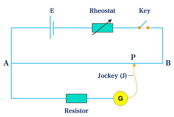
- A long, uniform resistance wire is connected to a constant e.m.f. supply, creating a steady potential gradient along its length.
- When a known e.m.f. (or voltage) is applied to a portion of the wire, the point at which no current flows through the galvanometer is called the null point.
- At this point, the potential difference across the wire segment equals the unknown e.m.f.
\( \mathrm{\dfrac{V_1}{V_2} = \dfrac{l_1}{l_2}} \)
or for comparing an unknown e.m.f. \( \mathrm{\varepsilon_x} \) with a standard cell \( \mathrm{\varepsilon_s} \):
\( \mathrm{\dfrac{\varepsilon_x}{\varepsilon_s} = \dfrac{l_x}{l_s}} \)
Where:
- \( \mathrm{l_x} \): length along potentiometer wire at balance (null) point for unknown cell.
- \( \mathrm{l_s} \): length at balance point for standard cell.
- \( \mathrm{\varepsilon_x, \varepsilon_s} \): unknown and standard e.m.f.s respectively.
Principle of Operation:
- The potential difference across any portion of the wire is proportional to its length (since the wire is uniform).
- By finding the balance point (no current in galvanometer), the two voltages are equal — allowing comparison or measurement of unknown voltage.
- Because no current flows through the unknown source at balance, the measurement is precise and unaffected by internal resistance.
Key Idea:
The potentiometer compares potential differences using a balance method — eliminating current flow through the device being measured, ensuring an accurate measurement of e.m.f.
Applications of the Potentiometer:
- Comparing the e.m.f.s of two cells.
- Measuring the internal resistance of a cell.
- Calibrating voltmeters and ammeters.
Potential Divider vs Potentiometer
| Aspect | Potential Divider | Potentiometer |
|---|---|---|
| Purpose | To produce a variable or specific output voltage from a fixed supply. | To compare or measure unknown potential differences or e.m.f.s. |
| Components | Two or more resistors (or sensors) in series. | Long uniform resistance wire with sliding contact. |
| Working Principle | Voltage divides in proportion to resistance values. | Potential difference across wire proportional to its length; balance gives equality of voltages. |
| Current through measured device | Current flows through the output circuit. | No current flows through the device at balance point → accurate measurement. |
| Main Equation | \( \mathrm{V_2 = \dfrac{R_2}{R_1 + R_2}V} \) | \( \mathrm{\dfrac{\varepsilon_x}{\varepsilon_s} = \dfrac{l_x}{l_s}} \) |
| Example Application | LDR/thermistor circuits, audio controls. | Comparison of e.m.f.s, internal resistance measurement. |
Example
In a potentiometer circuit, a standard cell of e.m.f. \( \mathrm{1.08 \, V} \) balances at a length of \( \mathrm{60.0 \, cm} \), while an unknown cell balances at \( \mathrm{45.0 \, cm.} \) Find the e.m.f. of the unknown cell.
▶️ Answer / Explanation
Using \( \mathrm{\dfrac{\varepsilon_x}{\varepsilon_s} = \dfrac{l_x}{l_s}} \):
\( \mathrm{\varepsilon_x = \varepsilon_s \times \dfrac{l_x}{l_s} = 1.08 \times \dfrac{45.0}{60.0} = 0.81 \, V.} \)
Hence, the e.m.f. of the unknown cell is \( \mathrm{0.81 \, V.} \)
Example
Explain why no current flows through the galvanometer when the potentiometer is balanced (at the null point).
▶️ Answer / Explanation
At the balance (null) point, the potential difference across the wire segment equals the e.m.f. of the cell connected. Since both sides of the galvanometer are at the same potential, there is no potential difference — and thus, no current flows.
Hence, balance ensures the measurement of true e.m.f. (not affected by internal resistance).
Use of a Galvanometer in Null Methods
A galvanometer is a very sensitive instrument used to detect small currents and to determine whether current is flowing in a circuit branch. In null methods, it is used to find the condition of zero current flow — the null point — in order to measure or compare potential differences accurately.
Principle of a Null Method: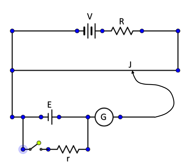
- In a null method (e.g., potentiometer experiment), a galvanometer connects between two points in a circuit.
- The galvanometer indicates when there is a potential difference between those points.
- At the null point, there is no potential difference — meaning no current flows through the galvanometer.
- At this point, the two voltages being compared are exactly equal.
Why a Null Method is Accurate:
- When the galvanometer shows zero deflection, there is no current through the cell being measured.
- Thus, the internal resistance of the cell does not affect the result — ensuring the true e.m.f. is measured.
- This makes the null method much more precise than direct voltmeter measurements.
In a null method, the galvanometer detects the balance point (no current), which signifies equal potential differences in two parts of the circuit. This allows accurate comparison or measurement of e.m.f.s.
Example
Explain the role of the galvanometer when comparing two cells using a potentiometer.
▶️ Answer / Explanation
The galvanometer is connected between the potentiometer wire and the terminal of the cell being tested. As the contact point on the wire is moved, the galvanometer shows deflection, indicating current flow. The null point occurs when deflection is zero — meaning the potential difference across the wire segment equals the e.m.f. of the cell.
At this point, the two e.m.f.s are balanced, and no current flows through the galvanometer.
Example
Why is the null point essential in a potentiometer experiment?
▶️ Answer / Explanation
At the null point, the two voltages being compared are equal, and no current flows through the galvanometer or the cell under test. This ensures that there is no energy loss due to internal resistance, making the comparison exact and eliminating measurement errors.
Hence, the null point allows precise comparison of e.m.f.s or potential differences.
Use of Thermistors in Potential Divider Circuits
Thermistors and LDRs are variable resistors whose resistance depends on temperature and light intensity respectively. They can be used in potential divider circuits to produce an output voltage that varies automatically with environmental changes.
Principle of Operation: 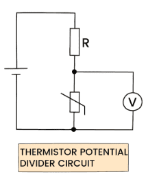
\( \mathrm{V_{out} = \dfrac{R_2}{R_1 + R_2} \, V_{in}} \)
By placing a thermistor or LDR as either \( \mathrm{R_1} \) or \( \mathrm{R_2} \), the output voltage changes when temperature or light changes.
Thermistor in a Potential Divider (Temperature-Dependent Output)
- A thermistor has a negative temperature coefficient (NTC) — its resistance decreases as temperature increases.
- Used in circuits where output voltage must vary with temperature (e.g., thermostats, automatic fans).
Case 1: Thermistor as Lower Resistor (R₂)
- When temperature increases → \( \mathrm{R_2} \) decreases → output voltage \( \mathrm{V_{out}} \) decreases.
- Used in temperature-sensing circuits (e.g., turns fan ON at high temperature).
Case 2: Thermistor as Upper Resistor (R₁)
- When temperature increases → \( \mathrm{R_1} \) decreases → \( \mathrm{V_{out}} \) increases.
- Used when a rising temperature should increase output voltage (e.g., fire alarm trigger).
Example
A potential divider has a thermistor (R₂) and a fixed resistor (R₁). The output voltage \( \mathrm{V_{out}} \) is connected to a fan control unit.
▶️ Answer / Explanation
At low temperatures: The thermistor has high resistance, so \( \mathrm{V_{out}} \) is high (since more voltage drops across it). At high temperatures: The thermistor’s resistance falls, so \( \mathrm{V_{out}} \) decreases. The control circuit detects this change and switches on the fan when \( \mathrm{V_{out}} \) drops below a set value.
Hence, the circuit automatically responds to temperature changes.
Light-Dependent Resistor (LDR) in a Potential Divider (Light-Dependent Output)
- An LDR’s resistance decreases as light intensity increases.
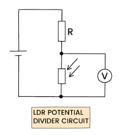
- Used in circuits where voltage output varies with brightness (e.g., automatic streetlights, light sensors).
Case 1: LDR as Lower Resistor (R₂)
- As light intensity increases → \( \mathrm{R_2} \) decreases → output voltage \( \mathrm{V_{out}} \) decreases.
- Used in automatic streetlight circuits where the lamp turns ON when light intensity falls (output voltage increases).
Case 2: LDR as Upper Resistor (R₁)
- As light intensity increases → \( \mathrm{R_1} \) decreases → output voltage \( \mathrm{V_{out}} \) increases.
- Used in light sensors where higher light should increase voltage (e.g., brightness meters).
Example
An LDR and a fixed resistor form a potential divider. The output \( \mathrm{V_{out}} \) is connected to a transistor that switches a lamp on or off depending on light level.
▶️ Answer / Explanation
During the day: High light intensity → LDR resistance is low → \( \mathrm{V_{out}} \) is low → transistor remains off → lamp off.
At night: Low light intensity → LDR resistance increases → \( \mathrm{V_{out}} \) rises → transistor switches on → lamp turns on automatically.
Hence, the circuit turns lights on when it gets dark, using an LDR as the light sensor.