Direction of Force on a Moving Charge in a Magnetic Field
A charged particle moving through a magnetic field experiences a force. This force is always perpendicular to both:
- the direction of motion of the charge, and
- the magnetic field direction.
This is known as the motor effect for charges.
Right-Hand Rule for Positive Charges
Thumb → direction of velocity (motion of the charge) First finger → direction of magnetic field (from N to S) Middle finger → direction of force
Important: For a negative charge, the force direction is opposite to that predicted by the right-hand rule.
Key Points:
- A stationary charge in a magnetic field feels no force (because velocity = 0).
- Force is maximum when velocity is perpendicular to the field.
- Force is zero when the charge moves parallel to the field (θ = 0° or 180°).
- The force causes charges to move in a circular or helical path.
Magnitude of Force:
\( \mathrm{F = Bqv\sin\theta} \)
Example
A positive charge moves to the right through a magnetic field directed into the page. What is the direction of the force?
▶️ Answer / Explanation
Use the right-hand rule:
- Thumb → right (velocity)
- First finger → into page (field)
- Middle finger → points upward
Force acts upward.
Example
An electron moves north in a magnetic field directed east. Determine the direction of the force on the electron.
▶️ Answer / Explanation
For a positive charge using right-hand rule:
- Thumb → north (velocity)
- First finger → east (field)
- Middle finger → points downward
But the charge is an electron, so reverse the direction:
Force acts upward.
Example
A proton moves at 90° to a magnetic field and experiences a force that deflects it out of the page. If the proton’s velocity is upward, determine the direction of the magnetic field.
▶️ Answer / Explanation
The force direction is out of the page.
Using right-hand rule (positive charge):
- Middle finger → out of page (force)
- Thumb → upward (velocity)
- First finger must point → left
The magnetic field is directed to the left.
Force on a Moving Charge: \( \mathrm{F = BQv \sin\theta} \)
A charged particle moving through a magnetic field experiences a magnetic force. The size of this force is given by: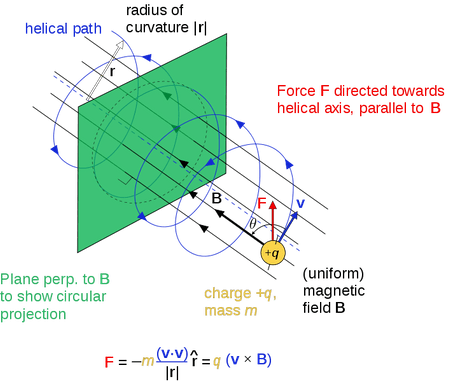
\( \mathrm{F = B Q v \sin\theta} \)
- \( \mathrm{F} \) = magnetic force (N)
- \( \mathrm{B} \) = magnetic flux density (T)
- \( \mathrm{Q} \) = charge of particle (C)
- \( \mathrm{v} \) = speed of particle (m s⁻¹)
- \( \mathrm{\theta} \) = angle between velocity and magnetic field
Key Understanding:
- Force is maximum when the charge moves perpendicular to the field (\( \mathrm{\theta = 90^\circ} \), \( \mathrm{\sin\theta = 1} \)).
- Force is zero when the charge moves parallel to the field (\( \mathrm{\theta = 0^\circ} \), \( \mathrm{\sin\theta = 0} \)).
- Force acts perpendicular to both the velocity and the magnetic field → resulting in circular or helical motion.
- Direction is determined using the right-hand rule (reverse for negative charges).
Example
An electron moves at \( \mathrm{3.0\times10^6\ m\,s^{-1}} \) perpendicular to a magnetic field of \( \mathrm{0.40\ T} \). The charge on the electron is \( \mathrm{1.6\times10^{-19}\ C} \). Find the magnitude of the force.
▶️ Answer / Explanation
Since the motion is perpendicular, \( \mathrm{\sin\theta = 1} \).
\( \mathrm{F = BQv = 0.40 \times 1.6\times10^{-19} \times 3.0\times10^6} \)
\( \mathrm{F = 1.92\times10^{-13}\ N} \)
Force = \( \mathrm{1.9\times10^{-13}\ N} \)
Example
A proton moves at an angle of 60° to a magnetic field of 0.20 T. Its speed is \( \mathrm{2.5\times10^5\ m\,s^{-1}} \) and charge is \( \mathrm{1.6\times10^{-19}\ C} \). Calculate the force on it.
▶️ Answer / Explanation
Use:
\( \mathrm{F = BQv \sin\theta} \)
\( \mathrm{F = 0.20 \times 1.6\times10^{-19} \times 2.5\times10^5 \times \sin 60^\circ} \)
Since \( \mathrm{\sin 60^\circ = 0.866} \):
\( \mathrm{F = 0.20 \times 1.6\times10^{-19} \times 2.5\times10^5 \times 0.866} \)
\( \mathrm{F \approx 6.9\times10^{-15}\ N} \)
Force ≈ \( \mathrm{6.9\times10^{-15}\ N} \)
Example
An alpha particle (charge \( \mathrm{+3.2\times10^{-19}\ C} \)) moves at \( \mathrm{5.0\times10^6\ m\,s^{-1}} \) through a magnetic field of \( \mathrm{0.15\ T} \). The angle between its velocity and the field is 30°. Calculate the magnetic force.
▶️ Answer / Explanation
Use:
\( \mathrm{F = BQv \sin\theta} \)
\( \mathrm{F = 0.15 \times 3.2\times10^{-19} \times 5.0\times10^6 \times \sin 30^\circ} \)
Since \( \mathrm{\sin 30^\circ = 0.5} \):
\( \mathrm{F = 0.15 \times 3.2\times10^{-19} \times 5.0\times10^6 \times 0.5} \)
\( \mathrm{F = 1.2\times10^{-13}\ N} \)
Force = \( \mathrm{1.2\times10^{-13}\ N} \)
The Hall Effect and the Hall Voltage
The Hall effect occurs when a current-carrying conductor or semiconductor is placed in a magnetic field that is perpendicular to the direction of the current. The moving charge carriers experience a magnetic force that pushes them to one side of the material, creating a measurable potential difference called the Hall voltage.
Origin of the Hall Voltage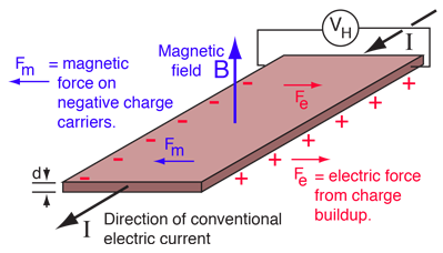
- Consider a flat conductor of thickness \( \mathrm{t} \) carrying a current \( \mathrm{I} \) in one direction.
- A magnetic field \( \mathrm{B} \) is applied perpendicular to the current.
- Charge carriers (electrons for metals, holes for p-type semiconductors) move with drift velocity \( \mathrm{v_d} \).
- The magnetic field exerts a force on each moving charge:
\( \mathrm{F = BQv_d} \)
- This force pushes the charges sideways.
- Charges accumulate on one side → one side becomes negatively charged, the opposite side positively charged.
- This separation of charge creates an electric field called the Hall field.
- A potential difference (Hall voltage \( \mathrm{V_H} \)) develops across the conductor.
- The Hall voltage increases until electric force balances magnetic force.
Balance Condition:
Magnetic force = Electric force \( \mathrm{B Q v_d = Q E_H} \)
So:
\( \mathrm{E_H = B v_d} \)
The Hall voltage is:
\( \mathrm{V_H = E_H \, t = B v_d t} \)
Derivation of the Hall Voltage Formula

Current is given by:
\( \mathrm{I = n A Q v_d} \)
- \( \mathrm{n} \) = number density of charge carriers (m⁻³)
- \( \mathrm{A} \) = cross-sectional area
- \( \mathrm{Q} \) = charge of each carrier
- \( \mathrm{v_d} \) = drift velocity
For a slab of width \( \mathrm{w} \) and thickness \( \mathrm{t} \):
\( \mathrm{A = w t} \)
Thus:
\( \mathrm{v_d = \dfrac{I}{n w t Q}} \)
Substitute into \( \mathrm{V_H = B v_d t} \):
\( \mathrm{V_H = B \left(\dfrac{I}{n w t Q}\right)t} \)
\( \mathrm{V_H = \dfrac{B I}{n Q w}} \)
For a strip where width \( \mathrm{w} \) is not involved in measurement, we write the final standard form:
\( \mathrm{V_H = \dfrac{B I}{n t Q}} \)
- \( \mathrm{V_H} \) = Hall voltage
- \( \mathrm{B} \) = magnetic flux density
- \( \mathrm{I} \) = current
- \( \mathrm{n} \) = carrier number density
- \( \mathrm{t} \) = thickness of the conductor
- \( \mathrm{Q} \) = charge of carrier (usually \( \mathrm{e = 1.6\times10^{-19}\ C} \))
Example
A conductor of thickness \( \mathrm{2.0\times10^{-3}\ m} \) carries a current of 4 A in a magnetic field of 0.50 T. The charge carrier density is \( \mathrm{8.0\times10^{28}\ m^{-3}} \). Find the Hall voltage.
▶️ Answer / Explanation
Use:
\( \mathrm{V_H = \dfrac{B I}{n t Q}} \)
Substitute:
\( \mathrm{V_H = \dfrac{0.50 \times 4}{(8.0\times10^{28})(2.0\times10^{-3})(1.6\times10^{-19})}} \)
\( \mathrm{V_H = 7.8\times10^{-9}\ V} \)
Hall voltage = \( \mathrm{7.8\times10^{-9}\ V} \)
Example
If the magnetic field is doubled in the previous example, what happens to the Hall voltage?
▶️ Answer / Explanation
The formula is:
\( \mathrm{V_H \propto B} \)
So doubling \( \mathrm{B} \) doubles \( \mathrm{V_H} \).
New Hall voltage = \( \mathrm{1.56\times10^{-8}\ V} \)
Example
A thin semiconductor slice of thickness \( \mathrm{1.0\times10^{-4}\ m} \) carries a current of 12 A. A magnetic field of 0.80 T is applied perpendicular to the slice. The measured Hall voltage is \( \mathrm{0.040\ V} \). Determine the number density of charge carriers.
▶️ Answer / Explanation
Use:
\( \mathrm{n = \dfrac{B I}{t Q V_H}} \)
Substitute:
\( \mathrm{n = \dfrac{0.80 \times 12}{(1.0\times10^{-4})(1.6\times10^{-19})(0.040)}} \)
\( \mathrm{n = 1.5\times10^{23}\ m^{-3}} \)
Carrier density = \( \mathrm{1.5\times10^{23}\ m^{-3}} \)
Use of a Hall Probe to Measure Magnetic Flux Density
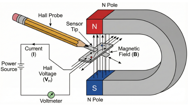
A Hall probe is a device that uses the Hall effect to measure the strength of a magnetic field (magnetic flux density, \( \mathrm{B} \)). It works by detecting the Hall voltage produced when a current-carrying conductor or semiconductor is placed in a magnetic field.
How a Hall Probe Works
- A thin semiconductor strip is supplied with a constant current \( \mathrm{I} \).
- When the strip is placed in a magnetic field perpendicular to the current direction, the Hall effect causes a sideways force on moving charge carriers.
- This creates a measurable potential difference — the Hall voltage \( \mathrm{V_H} \) — across the strip.
- The Hall voltage is proportional to the magnetic flux density:
\( \mathrm{V_H = \dfrac{B I}{n t q}} \)
By measuring \( \mathrm{V_H} \), the Hall probe can determine \( \mathrm{B} \) accurately.
Using a Hall Probe
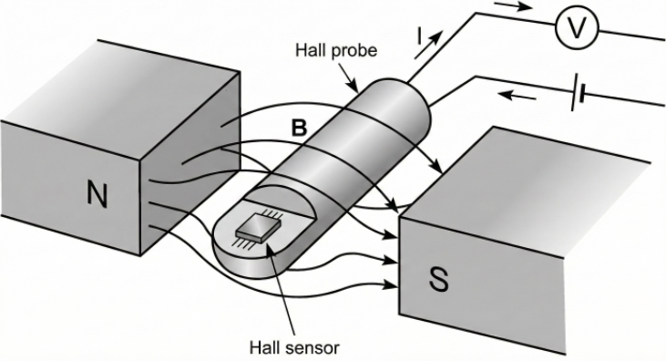
- The Hall probe is placed so that its sensing surface is perpendicular to the magnetic field.
- The probe is connected to a voltmeter or electronic meter that reads the Hall voltage.
- The device is often calibrated so that it directly displays magnetic flux density in tesla (T) or millitesla (mT).
- The reading changes sign depending on field direction (north–south reversal).
Orientation Matters:
Maximum reading occurs when the plane of the Hall element is at right-angles to the magnetic field. If the probe is tilted, the measured flux density decreases according to \( \mathrm{B\cos\theta} \).
Advantages of a Hall Probe
- Can measure strong magnetic fields where compasses or iron filings fail.
- Allows measurement of magnitude and direction of the field.
- Very sensitive (especially semiconductor probes).
- Can measure rapidly changing magnetic fields.
Example
A Hall probe is placed in a magnetic field and its sensing face is perpendicular to the field. Why is this orientation necessary?
▶️ Answer / Explanation
The Hall voltage is proportional to the perpendicular component of the magnetic field. To maximise the Hall effect (and reading), the sensing surface must be at right-angles to the field.
Example
A Hall probe gives a reading of 0.32 mT when oriented correctly in a magnetic field. When it is tilted so that the face is at 60° to the field, what reading will it give?
▶️ Answer / Explanation
Only the perpendicular component is measured:
\( \mathrm{B_{\text{measured}} = B \cos\theta} \)
\( \mathrm{B_{\text{measured}} = 0.32\times10^{-3} \times \cos 60^\circ} \)
\( \mathrm{= 0.32\times10^{-3} \times 0.5 = 0.16\ mT} \)
Measured field = 0.16 mT
Example
A Hall probe uses a semiconductor of thickness \( \mathrm{1.5\times10^{-4}\ m} \) with charge carrier density \( \mathrm{4.0\times10^{22}\ m^{-3}} \). A constant current of 18 mA flows through the probe. In a certain magnetic field, the Hall voltage measured is 0.020 V. Calculate the magnetic flux density.
▶️ Answer / Explanation
Use the Hall voltage formula:
\( \mathrm{V_H = \dfrac{B I}{n t q}} \)
Rearrange:
\( \mathrm{B = \dfrac{V_H \, n t q}{I}} \)
Substitute:
\( \mathrm{B = \dfrac{0.020 \times (4.0\times10^{22}) \times (1.5\times10^{-4}) \times (1.6\times10^{-19})}{18\times10^{-3}}} \)
\( \mathrm{B = 1.07\ T} \)
Magnetic flux density ≈ 1.07 T
Motion of a Charged Particle in a Uniform Magnetic Field (Perpendicular Entry)
When a charged particle moves into a uniform magnetic field perpendicular to its velocity, it experiences a magnetic force that is always perpendicular to its motion.
This perpendicular force causes the particle to move in a circular path.
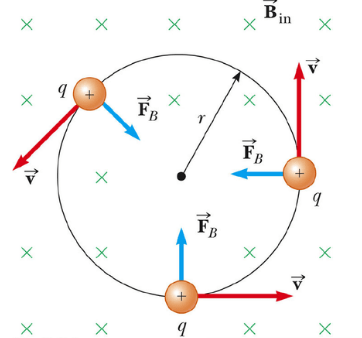
Why Circular Motion Occurs
- The magnetic force on a moving charge is:
\( \mathrm{F = BQv} \)
- This force is always perpendicular to the velocity.
- A force perpendicular to velocity does not change speed — only direction.
- Thus, the magnetic force acts as a centripetal force.
\( \mathrm{BQv = \dfrac{mv^2}{r}} \)
The resulting path is a uniform circle.
Radius of the Circular Path

\( \mathrm{r = \dfrac{mv}{BQ}} \)
- Lighter particles → smaller radius
- Faster particles → larger radius
- Stronger magnetic field → tighter circle
- Greater charge → tighter circle
Key Characteristics of the Motion
- Speed remains constant (force is perpendicular to motion).
- Velocity direction changes continuously → circular motion.
- Angular speed \( \mathrm{\omega = \dfrac{v}{r} = \dfrac{BQ}{m}} \)
- Time period:
\( \mathrm{T = \dfrac{2\pi m}{BQ}} \)
- Direction of rotation depends on charge sign:
- Positive charge → direction given by right-hand rule
- Negative charge → rotates in opposite direction
Example
A proton enters a uniform magnetic field perpendicular to its velocity. Describe its motion.
▶️ Answer / Explanation
The proton experiences a force perpendicular to its velocity, causing it to move in a circular path. Its speed remains constant, but its direction changes continuously.
Example
An electron enters a magnetic field at 90° to the field lines. How is its circular motion different from that of a proton?
▶️ Answer / Explanation
- An electron has a negative charge → force direction reverses.
- The electron moves in the opposite sense (clockwise/anticlockwise) compared to the proton.
- Because the electron has a much smaller mass, its radius
\( \mathrm{r = \dfrac{mv}{BQ}} \)
is much smaller.
The electron travels in a smaller circle and opposite direction to a proton.
Example
An alpha particle (\( \mathrm{Q = 3.2 \times 10^{-19}\ C} \)) with speed \( \mathrm{1.0\times10^6\ m\,s^{-1}} \) enters a \( \mathrm{0.40\ T} \) magnetic field perpendicular to its motion. Calculate the radius of its circular path. (The mass of an alpha particle is \( \mathrm{6.64\times10^{-27}\ kg} \)).
▶️ Answer / Explanation
Use:
\( \mathrm{r = \dfrac{mv}{BQ}} \)
\( \mathrm{r = \dfrac{6.64\times10^{-27} \times 1.0\times10^6}{0.40 \times 3.2\times10^{-19}}} \)
\( \mathrm{r = \dfrac{6.64\times10^{-21}}{1.28\times10^{-19}}} \)
\( \mathrm{r = 0.052\ m} \)
Radius = 0.052 m
Velocity Selection Using Electric and Magnetic Fields
A velocity selector uses crossed electric and magnetic fields to allow only charged particles with a specific velocity to pass through undeflected. All other particles experience a net force and are deflected away.
How Velocity Selection Works
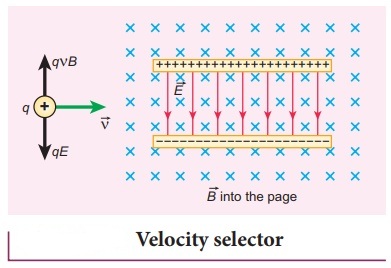
- A uniform electric field \( \mathrm{E} \) is applied between two parallel plates → produces an electric force
\( \mathrm{F_E = QE} \)
- A uniform magnetic field \( \mathrm{B} \) is applied perpendicular to both the plates and the particle motion → produces a magnetic force
\( \mathrm{F_B = BQv} \)
- The two forces act in opposite directions.
Condition for no deflection: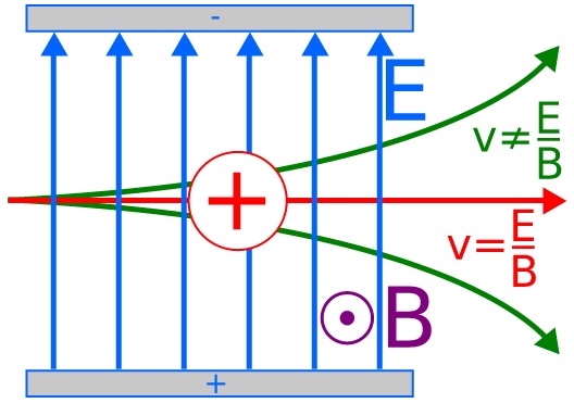
\( \mathrm{F_E = F_B} \)
Substitute:
\( \mathrm{QE = BQv} \)
Cancel \( \mathrm{Q} \):
\( \mathrm{v = \dfrac{E}{B}} \)
Only particles with velocity \( \mathrm{v = E/B} \) travel straight.
Slower or faster particles experience a net force and are deflected away.
Key Features of a Velocity Selector:
- Works only when \( \mathrm{E} \) and \( \mathrm{B} \) fields are perpendicular to each other and to particle motion.
- The selected velocity does not depend on charge or mass → only on \( \mathrm{E/B} \).
- Used in mass spectrometers and particle accelerators.
Applications:

- Mass spectrometer — ensures all ions entering the magnetic chamber have the same velocity.
- Charged particle detection — isolate particles of a specific speed.
- Plasma experiments — control particle streams.
Example
A proton enters a velocity selector and moves undeflected. What does this tell you about its speed?
▶️ Answer / Explanation
The electric and magnetic forces are balanced. Thus, the proton’s speed is:
\( \mathrm{v = \dfrac{E}{B}} \)
Its velocity matches the selector’s chosen speed.
Example
A velocity selector has an electric field of \( \mathrm{4.0\times10^4\ V\,m^{-1}} \) and a magnetic field of \( \mathrm{0.20\ T} \). Find the velocity of particles that will pass through undeflected.
▶️ Answer / Explanation
Use:
\( \mathrm{v = \dfrac{E}{B}} \)
\( \mathrm{v = \dfrac{4.0\times10^4}{0.20} = 2.0\times10^5\ m\,s^{-1}} \)
Selected velocity = \( \mathrm{2.0\times10^5\ m\,s^{-1}} \)
Example
An ion enters a velocity selector with electric field \( \mathrm{6.0\times10^4\ V\,m^{-1}} \) and magnetic field \( \mathrm{0.30\ T} \). If the ion is observed to bend upward, determine whether its speed is too high or too low.
▶️ Answer / Explanation
The electric field pushes charges in one direction; the magnetic field pushes them in the opposite direction.
If the ion bends upward, it means:
- One of the forces is stronger → imbalance.
- If the magnetic force dominates, the ion curves in the magnetic-force direction.
Since magnetic force = \( \mathrm{BQv} \):
If bending occurs, \( \mathrm{BQv > QE} \) → \( \mathrm{v > \dfrac{E}{B}} \).
The ion’s speed is greater than the selected velocity.