Magnetic Flux
Magnetic flux is a measure of how much magnetic field passes through a given area. It describes the total “flow” of magnetic field lines through a surface.
Definition:
Magnetic flux \( \mathrm{\Phi} \) is defined as the product of the magnetic flux density and the area that is perpendicular to the magnetic field.

\( \mathrm{\Phi = B A} \)
- \( \mathrm{\Phi} \) = magnetic flux (weber, Wb)
- \( \mathrm{B} \) = magnetic flux density (tesla, T)
- \( \mathrm{A} \) = cross-sectional area perpendicular to the field (m²)
If the area is not perpendicular to the magnetic field, then only the perpendicular component counts:

\( \mathrm{\Phi = BA\cos\theta} \)
where \( \mathrm{\theta} \) is the angle between the field direction and the normal to the area.
Key Ideas:
- Magnetic flux increases when the field strength increases.
- Flux increases when a larger area is exposed to the field.
- Flux is maximum when the area is perpendicular to \( \mathrm{B} \).
- Flux is zero when the area is parallel to \( \mathrm{B} \).
Example
A magnetic field of \( \mathrm{0.50\ T} \) passes perpendicularly through an area of \( \mathrm{0.20\ m^2} \). Calculate the magnetic flux.
▶️ Answer / Explanation
\( \mathrm{\Phi = BA = 0.50 \times 0.20 = 0.10\ Wb} \)
Magnetic flux = 0.10 Wb
Example
A coil of cross-sectional area \( \mathrm{0.030\ m^2} \) is placed in a magnetic field of \( \mathrm{0.80\ T} \). The plane of the coil makes an angle of 60° with the magnetic field direction. Find the magnetic flux through the coil.
▶️ Answer / Explanation
The angle between field and normal = 30°.
\( \mathrm{\Phi = BA\cos\theta = 0.80 \times 0.030 \times \cos30^\circ} \)
\( \mathrm{\Phi = 0.024 \times 0.866 = 0.0208\ Wb} \)
Magnetic flux ≈ 0.0208 Wb
Example
A rectangular loop of area \( \mathrm{0.060\ m^2} \) is placed in a magnetic field. The magnetic flux through the loop is \( \mathrm{0.015\ Wb} \). If the field strength is increased to \( \mathrm{0.50\ T} \), what angle must the loop make with the field so that the flux remains unchanged?
▶️ Answer / Explanation
We need:
\( \mathrm{\Phi = BA\cos\theta = 0.015} \)
Substitute values:
\( \mathrm{0.015 = (0.50)(0.060)\cos\theta} \)
\( \mathrm{\cos\theta = \dfrac{0.015}{0.030} = 0.50} \)
So:
\( \mathrm{\theta = 60^\circ} \)
The loop must be tilted so its normal is 60° to the field.
Using the Magnetic Flux Formula \( \mathrm{\Phi = BA} \)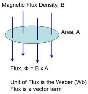
The magnetic flux \( \mathrm{\Phi} \) through a surface is given by:
\( \mathrm{\Phi = B A} \)
where:
- \( \mathrm{\Phi} \) = magnetic flux (Wb)
- \( \mathrm{B} \) = magnetic flux density (T)
- \( \mathrm{A} \) = area perpendicular to the magnetic field (m²)
Condition:
This formula applies when the area is fully perpendicular to the magnetic field.
If the area is tilted, only the perpendicular component contributes → then the formula becomes \( \mathrm{\Phi = BA\cos\theta} \). But for this syllabus point, we use the simple form \( \mathrm{\Phi = BA} \).
Example
A uniform magnetic field of \( \mathrm{0.60\ T} \) passes perpendicularly through a loop of area \( \mathrm{0.040\ m^2} \). Calculate the magnetic flux.
▶️ Answer / Explanation
\( \mathrm{\Phi = BA = 0.60 \times 0.040 = 0.024\ Wb} \)
Magnetic flux = 0.024 Wb
Example
A square coil of side 0.15 m is placed perpendicular to a magnetic field of magnitude \( \mathrm{0.20\ T} \). Find the magnetic flux through the coil.
▶️ Answer / Explanation
Area of square:
\( \mathrm{A = 0.15^2 = 0.0225\ m^2} \)
Flux:
\( \mathrm{\Phi = BA = 0.20 \times 0.0225 = 4.5\times10^{-3}\ Wb} \)
Magnetic flux = \( \mathrm{4.5\times10^{-3}\ Wb} \)
Example
A magnetic field of \( \mathrm{1.2\ T} \) passes perpendicularly through a circular coil producing a flux of \( \mathrm{0.018\ Wb} \). Calculate the radius of the coil.
▶️ Answer / Explanation
Use:
\( \mathrm{\Phi = BA} \Rightarrow \mathrm{A = \dfrac{\Phi}{B}} \)
\( \mathrm{A = \dfrac{0.018}{1.2} = 0.015\ m^2} \)
For circular area:
\( \mathrm{A = \pi r^2} \Rightarrow \mathrm{r = \sqrt{\dfrac{A}{\pi}}} \)
\( \mathrm{r = \sqrt{\dfrac{0.015}{3.1416}} = 0.069\ m} \)
Radius ≈ 0.069 m
Magnetic Flux Linkage
Magnetic flux linkage extends the idea of magnetic flux to a coil with multiple turns. It tells us how much total flux is linked with (cut by) all the turns of a coil.
Definition:
Magnetic flux linkage \( \mathrm{N\Phi} \) is the product of the number of turns in a coil \( \mathrm{N} \) and the magnetic flux \( \mathrm{\Phi} \) through each turn.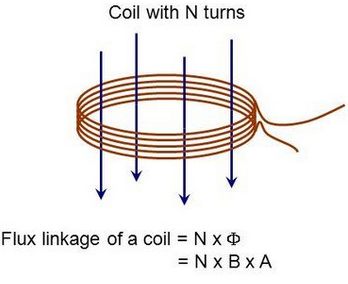
\( \mathrm{N\Phi = N B A} \quad \text{(if the coil area is perpendicular to the magnetic field)} \)
- \( \mathrm{N\Phi} \) = magnetic flux linkage (weber-turns, Wb)
- \( \mathrm{N} \) = number of turns
- \( \mathrm{\Phi} \) = flux through one turn (Wb)
- \( \mathrm{B} \) = magnetic flux density (T)
- \( \mathrm{A} \) = area of one turn (m²)
Why Flux Linkage Matters
- Induced emf depends on how fast flux linkage changes (Faraday’s law: \( \mathrm{E = -\dfrac{d(N\Phi)}{dt}} \)).
- Coils with more turns produce larger induced voltages.
- Flux linkage is used in transformers, generators, inductors, and AC machines.
Key Points
- If the coil is tilted by angle \( \mathrm{\theta} \), flux linkage becomes
\( \mathrm{N\Phi = NBA\cos\theta} \)
- More turns → more flux linkage → greater induced emf.
Example
A coil has 20 turns and each turn experiences a flux of \( \mathrm{5.0\times10^{-4}\ Wb} \). Calculate the flux linkage.
▶️ Answer / Explanation
\( \mathrm{N\Phi = N\Phi = 20 \times 5.0\times10^{-4} = 1.0\times10^{-2}\ Wb} \)
Flux linkage = \( \mathrm{1.0\times10^{-2}\ Wb} \)
Example
A coil has 50 turns and area \( \mathrm{0.012\ m^2} \). It is placed perpendicular to a magnetic field of \( \mathrm{0.30\ T} \). Find the flux linkage.
▶️ Answer / Explanation
Flux per turn:
\( \mathrm{\Phi = BA = 0.30 \times 0.012 = 0.0036\ Wb} \)
Flux linkage:
\( \mathrm{N\Phi = 50 \times 0.0036 = 0.18\ Wb} \)
Flux linkage = 0.18 Wb
Example
A 200-turn coil of area \( \mathrm{0.020\ m^2} \) is placed in a magnetic field of 0.50 T. The plane of the coil is tilted so that the angle between its normal and the field is 60°. Calculate the magnetic flux linkage.
▶️ Answer / Explanation
Flux per turn:
\( \mathrm{\Phi = BA\cos\theta = 0.50 \times 0.020 \times \cos60^\circ} \)
\( \mathrm{\Phi = 0.010 \times 0.50 = 0.005\ Wb} \)
Flux linkage:
\( \mathrm{N\Phi = 200 \times 0.005 = 1.0\ Wb} \)
Flux linkage = 1.0 Wb
Experiments Demonstrating Electromagnetic Induction
Electromagnetic induction occurs when a changing magnetic flux through a circuit produces an induced e.m.f. These experiments show how induction works, its direction, and the factors affecting its magnitude.
1. Experiment: A Changing Magnetic Flux Induces an e.m.f.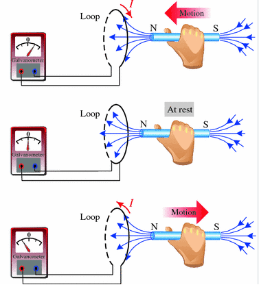
Apparatus:
- Coil connected to a sensitive galvanometer
- Bar magnet (or solenoid carrying AC)
- Connecting wires
Procedure:
- Move the bar magnet into the coil → galvanometer deflects → e.m.f. induced.
- Hold the magnet stationary inside the coil → no deflection → no induction (flux constant).
- Withdraw the magnet from the coil → galvanometer deflects in opposite direction.
Conclusion:
A changing magnetic flux through the coil induces an e.m.f.
2. Experiment: Direction of Induced e.m.f. Opposes the Change (Lenz’s Law)
Apparatus:
- Copper or aluminium ring
- Electromagnet or bar magnet
Procedure:
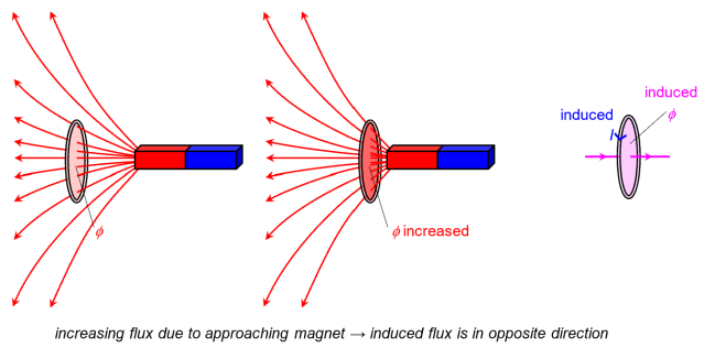
- Bring the north pole of a magnet quickly towards a copper ring → ring generates an induced current.
- The induced current creates its own magnetic field that repels the approaching magnet.
- Withdraw the magnet → induced field attracts the retreating magnet.
Conclusion (Lenz’s law):
The induced e.m.f. produces a current that opposes the change in magnetic flux producing it.
Statement:
Induced e.m.f. opposes the change in flux → conservation of energy.
3. Experiment: Factors Affecting Magnitude of Induced e.m.f.
From Faraday’s Law:
\( \mathrm{E = – \dfrac{d(N\Phi)}{dt}} \)
A. Speed of Motion
- Move magnet faster into the coil → galvanometer deflects more → greater e.m.f.
B. Strength of Magnetic Field (B)
- Use a stronger magnet → greater change in flux → larger e.m.f.
C. Number of Turns (N)
- Use a coil with more turns → flux linkage increases → larger induced e.m.f.
D. Area of Coil (A)
- Use a coil with larger cross-sectional area → more flux cutting the coil → larger e.m.f.
E. Rate of Change of Magnetic Field
- Changing the magnetic field rapidly (e.g., using AC source) increases induced e.m.f.
Example
When a magnet is pushed slowly into a coil, the induced e.m.f. is small. Why does pushing it faster produce a larger e.m.f.?
▶️ Answer / Explanation
Because faster motion → larger rate of change of flux \( \mathrm{\dfrac{d\Phi}{dt}} \). Greater rate of change of flux → larger induced e.m.f. (Faraday’s law).
Example
When the north pole of a magnet approaches a coil, the galvanometer deflects left. When withdrawn, it deflects right. Explain this observation using Lenz’s law.
▶️ Answer / Explanation
The coil produces an induced current that opposes the change in flux:
- As the magnet approaches, the coil creates a north pole facing the magnet → repels → deflection left.
- When moving away, the coil creates a south pole facing the magnet → attracts → deflection right.
This behaviour follows Lenz’s law.
Example
A coil with 150 turns and area \( \mathrm{0.010\ m^2} \) is placed in a magnetic field that increases uniformly from 0.0 T to 0.40 T in 0.20 s. Calculate the induced e.m.f.
▶️ Answer / Explanation
Flux change per turn:
\( \mathrm{\Delta\Phi = BA = 0.40 \times 0.010 = 0.004\ Wb} \)
Total flux linkage:
\( \mathrm{N\Delta\Phi = 150 \times 0.004 = 0.60\ Wb} \)
Use Faraday’s law:
\( \mathrm{E = \dfrac{\Delta(N\Phi)}{\Delta t} = \dfrac{0.60}{0.20} = 3.0\ V} \)
Induced e.m.f. = 3.0 V
Faraday’s and Lenz’s Laws of Electromagnetic Induction
Electromagnetic induction describes how a changing magnetic environment induces an e.m.f. in a circuit. Two fundamental laws govern this phenomenon: Faraday’s law and Lenz’s law.
Faraday’s Law
Faraday’s law gives the magnitude of the induced e.m.f.

\( \mathrm{E = -\dfrac{d(N\Phi)}{dt}} \)
- \( \mathrm{E} \) = induced e.m.f. (volts)
- \( \mathrm{N} \) = number of turns on the coil
- \( \mathrm{\Phi} \) = magnetic flux through each turn (Wb)
- \( \mathrm{N\Phi} \) = magnetic flux linkage
Key ideas:
- An e.m.f. is induced when magnetic flux linkage changes.
- Faster change in flux → larger induced e.m.f.
- More turns → larger induced e.m.f.
Lenz’s Law
Lenz’s law gives the direction of the induced e.m.f.
The induced e.m.f. is always in such a direction as to oppose the change in magnetic flux producing it.

Why?
- Prevents violation of conservation of energy.
- Induced current creates a magnetic field that tries to keep flux constant.
Interpretation of the Negative Sign in Faraday’s Law:
The “−” symbol represents Lenz’s law: opposition.
Together, the laws state:
- Magnitude: proportional to rate of change of flux linkage.
- Direction: opposes the flux change.
Example
A magnet is moved slowly into a coil and induces a small e.m.f. If moved faster, the e.m.f. increases. Explain using Faraday’s law.
▶️ Answer / Explanation
According to Faraday’s law:
\( \mathrm{E \propto \dfrac{d(N\Phi)}{dt}} \)
Faster motion → flux changes more rapidly → greater \( \mathrm{\dfrac{d\Phi}{dt}} \) → larger induced e.m.f.
Example
A coil is placed near a bar magnet. When the magnet approaches, the induced current direction opposes the magnet’s motion. Explain why this happens using Lenz’s law.
▶️ Answer / Explanation
Lenz’s law states the induced current opposes the change causing it. Approaching magnet increases flux through the coil.
- To oppose the increase, the coil produces a magnetic field opposing the magnet.
- This results in a repulsive force → current direction chosen to create that opposing field.
Thus, direction of induced current prevents the flux rising too quickly.
Example
The magnetic flux linking a 250-turn coil changes from \( \mathrm{0.0025\ Wb} \) to \( \mathrm{0.0060\ Wb} \) in \( \mathrm{0.040\ s} \). Calculate the magnitude of the induced e.m.f. and state its polarity using Lenz’s law.
▶️ Answer / Explanation
Flux linkage change:
\( \mathrm{\Delta(N\Phi) = 250(0.0060 – 0.0025)} \)
\( \mathrm{\Delta(N\Phi) = 250 \times 0.0035 = 0.875\ Wb} \)
Induced e.m.f.:
\( \mathrm{E = \dfrac{\Delta(N\Phi)}{\Delta t} = \dfrac{0.875}{0.040} = 21.9\ V} \)
Magnitude = 21.9 V
Direction (Lenz’s law):
- If flux increased, induced e.m.f. acts to oppose this increase → creates a field opposing the applied field.
<liTherefore, polarity is arranged so that current creates an opposing magnetic field.