Half-Wave and Full-Wave Rectification
Rectification is the process of converting an alternating current (AC) signal into a unidirectional (DC) signal. The easiest way to distinguish between half-wave and full-wave rectification is by examining their voltage–time graphs.
Half-Wave Rectification
- Only one half-cycle (usually the positive half) of the AC waveform is allowed through.
- The diode blocks the negative half-cycle completely → output voltage is zero during negative cycle.
- Graph shows:
- Positive sine pulses
- Flat line (zero output) during each negative half-cycle

Full-Wave Rectification
- Both halves of the AC waveform are used.
- The negative half-cycle is inverted to become positive.
- Graph shows:
- Positive output for both halves
- Twice as many pulses per cycle compared to half-wave

Graphical Comparison (Conceptual Description)
- Half-wave: \( \mathrm{V(t) = V_0 \sin(\omega t)} \) for positive half \( \mathrm{V(t) = 0} \) for negative half → Output has gaps.
- Full-wave: \( \mathrm{V(t) = |V_0 \sin(\omega t)|} \) → No gaps; negative half is flipped.
Example
A student observes a rectified AC signal on an oscilloscope. The trace shows positive pulses with flat zero regions between them. Identify the type of rectification.
▶️ Answer / Explanation
This waveform shows gaps between pulses → output is zero during half the cycle.
Therefore, it is half-wave rectification.
Example
An oscilloscope displays a waveform where all cycles of the sine wave appear above the time axis, with no zero gaps. Explain what type of rectification is occurring and why.
▶️ Answer / Explanation
All negative cycles have been inverted into positive cycles, and there are no zero intervals.
This is characteristic of full-wave rectification, where a diode bridge or two diodes in a centre-tap transformer invert the negative half-cycle.
Example
A rectified waveform has twice the frequency of the original AC supply. The waveform is always positive and has no gaps. Identify the type of rectification and justify your answer graphically.
▶️ Answer / Explanation
The doubling of frequency indicates that every half-cycle (positive and negative) produces a pulse.
Since there are no zero intervals and all pulses are above the axis, the waveform is:
Full-wave rectification
Graphically, full-wave rectification produces twice as many peaks per period as the original AC input because both halves of the sine wave are used.
Use of a Single Diode for Half-Wave Rectification
A single diode can be used to convert an alternating current (AC) into a unidirectional (DC) output. This process is known as half-wave rectification.
How It Works:
- A diode conducts current only when it is forward biased (positive on the anode, negative on the cathode).
- During the positive half-cycle of the AC supply, the diode is forward biased → current flows → output follows the positive sine wave.
- During the negative half-cycle, the diode is reverse biased → no current flows → output is zero.

Result:
Only the positive half of the AC waveform appears at the output. The negative half is completely blocked → producing half-wave rectification.
Graphically:
- Input: full sine wave (positive + negative halves).
- Output: positive “humps” separated by flat zero intervals.
Advantages:
- Simple circuit (only one diode).
- Low cost.
Disadvantages:
- Poor efficiency — half the input power is lost.
- Large ripple (output not smooth).
Example
Explain why a single diode gives zero output during the negative half-cycle of an AC input.
▶️ Answer / Explanation
During the negative half-cycle, the anode of the diode becomes negative relative to the cathode. This reverse biases the diode, preventing current flow. Therefore, the output voltage is zero.
Example
A single diode is connected to an AC source. Describe the shape of the output waveform and explain why it appears this way.
▶️ Answer / Explanation
The output consists of only the positive half-cycles of the sine wave, with zero output in between.
Reason: the diode conducts only when forward biased (positive half-cycle), but blocks the current when reverse biased (negative half-cycle), producing gaps in the waveform.
Example
An AC input has a peak voltage of 12 V. A single diode is used for half-wave rectification. Sketch and describe the output waveform and determine the peak output voltage assuming an ideal diode.
▶️ Answer / Explanation
Shape of output:
- Positive half-cycles appear unchanged.
- Negative half-cycles are completely absent (output = 0).
- Waveform looks like isolated positive humps.
Peak output voltage:
For an ideal diode, no voltage drop occurs → peak output = 12 V.
Output peak = 12 V
Full-Wave Rectification Using a Four-Diode Bridge Rectifier
A bridge rectifier uses four diodes arranged in a specific configuration to convert both halves of an AC waveform into a unidirectional (positive) output. This makes it far more efficient than half-wave rectification.
How the Bridge Rectifier Works
A bridge rectifier has four diodes arranged in a diamond shape. During each half-cycle of the AC input, two of the four diodes conduct while the other two are reverse biased.
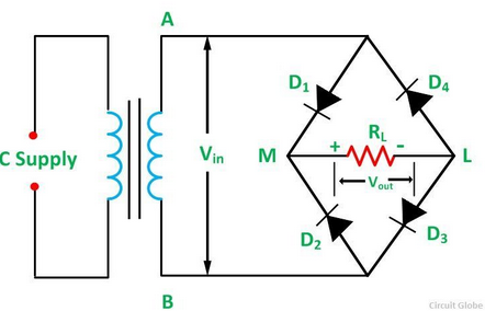
Positive Half-Cycle:
- The top of the AC supply becomes positive relative to the bottom.
- Diodes D1 and D2 conduct.
- Current flows through the load in one direction.
- Diodes D3 and D4 are reverse biased → they block current.
Negative Half-Cycle:
- The top of the AC supply becomes negative relative to the bottom.
- Diodes D3 and D4 conduct.
- Current again flows through the load in the SAME direction.
- D1 and D2 are now reverse biased → they block current.
Result:
Both halves of the AC input produce a positive output → full-wave rectification.
Graphically:
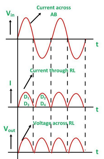
- Input: full sine wave
- Output: all positive humps, no zero intervals
- Output frequency = twice the input AC frequency
Advantages of the Bridge Rectifier:
- Uses both halves of AC waveform → higher efficiency
- No need for a centre-tapped transformer
- Smoother DC output compared to half-wave
Example
Explain why full-wave rectification produces twice as many output pulses as half-wave rectification.
▶️ Answer / Explanation
In a bridge rectifier, both positive and negative half-cycles are used. The negative half-cycle is inverted to become positive using two of the four diodes. Thus, each cycle produces two pulses → double the number in half-wave rectification.
Example
During the positive half-cycle of an AC supply feeding a bridge rectifier, only two of the diodes conduct. Name them and explain why the others do not conduct.
▶️ Answer / Explanation
During the positive half-cycle, diodes D1 and D2 become forward biased → they conduct.
Diodes D3 and D4 have their cathodes made more positive than their anodes during this part of the cycle → they are reverse biased → they do not conduct.
Example
An AC supply of peak voltage 18 V is connected to a bridge rectifier (ideal diodes). Describe the output waveform and determine the peak output voltage across the load.
▶️ Answer / Explanation
Output waveform:
- Every positive and negative half-cycle produces a positive pulse.
- The output voltage never goes negative.
- Pulses occur twice per AC cycle → doubled frequency.
Peak output voltage:
For ideal diodes, no voltage is lost → peak output = peak input.
\( \mathrm{V_{0,\text{out}} = 18\ V} \)
Peak output = 18 V
Smoothing a Rectified Output Using a Capacitor
After rectification (half-wave or full-wave), the output is still “pulsating DC.” A smoothing capacitor is connected in parallel with the load to reduce the size of these ripples and produce a smoother DC output.

How Smoothing Works:
- When the rectified voltage increases (during each peak), the capacitor charges up.
- When the rectified voltage falls (between peaks), the capacitor discharges slowly through the load.
- This discharge maintains the output voltage → smoothing the waveform.
The result is a DC voltage that still has some ripple, but the variations are much smaller.
Graphically:
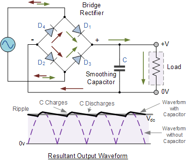
- Without capacitor → sharp peaks and deep valleys.
- With capacitor → voltage rises to a peak, then falls gradually (exponential discharge), then rises again.
- The ripple becomes smaller as smoothing improves.
Ripple Voltage:
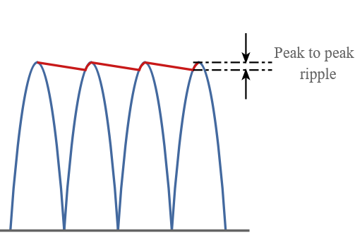
Ripple depends on how much the capacitor discharges between peaks.
Effect of Capacitance on Smoothing
Summary: Bigger C → better smoothing. | Effect of Load Resistance on Smoothing
Summary: Larger R → better smoothing. |
Time Constant and Smoothing
\( \mathrm{\tau = RC} \)
- Large \( \mathrm{\tau} \) → capacitor discharges slowly → smooth output.
- Small \( \mathrm{\tau} \) → capacitor discharges quickly → large ripple.
Example
A capacitor is connected across the output of a half-wave rectifier. The output voltage becomes smoother. Explain why the capacitor improves smoothing.
▶️ Answer / Explanation
The capacitor charges during the peak and discharges between peaks, supplying current to the load. This prevents the voltage from dropping to zero, reducing ripple and creating a smoother DC output.
Example
Two smoothing capacitors are tested: \( \mathrm{10\ \mu F} \) and \( \mathrm{470\ \mu F} \). Which gives a smoother output and why?
▶️ Answer / Explanation
The \( \mathrm{470\ \mu F} \) capacitor stores more charge and discharges more slowly, keeping the output voltage high between peaks. Therefore, it produces a much smoother DC output with less ripple.
Example
A full-wave rectifier outputs pulses at twice the mains frequency. The smoothing capacitor is \( \mathrm{220\ \mu F} \). Explain how decreasing the load resistance affects the ripple voltage.
▶️ Answer / Explanation
When the load resistance decreases, a larger current is drawn. The capacitor discharges more rapidly between the rectified peaks.
This causes the minimum voltage during each cycle to drop further → increasing the ripple voltage.
Because:
\( \mathrm{\tau = RC} \) decreases → faster discharge → poorer smoothing.
Thus, lower R → higher ripple → less effective smoothing.