Definition of Potential Difference
The potential difference (p.d.) across a component is defined as the energy transferred per unit charge when charge moves between two points in an electric circuit.
\( \mathrm{V = \dfrac{W}{Q}} \)
Where:
- \( \mathrm{V} \) = potential difference (volts, V)
- \( \mathrm{W} \) = electrical energy transferred (joules, J)
- \( \mathrm{Q} \) = charge moved (coulombs, C)
Explanation: If one coulomb of charge gains or loses one joule of energy while passing through a component, the potential difference across that component is 1 volt.
\( \mathrm{1 \ V = 1 \ \dfrac{J}{C}} \)
Potential difference measures how much energy is transferred by electrical charges — it represents the “energy per coulomb” provided or used by a component.
Example
A charge of \( \mathrm{8.0 \ C} \) passes through a resistor, and \( \mathrm{24 \ J} \) of energy is transferred as heat. Find the potential difference across the resistor.
▶️ Answer / Explanation
Using \( \mathrm{V = \dfrac{W}{Q}} \):
\( \mathrm{V = \dfrac{24}{8.0} = 3.0 \ V.} \)
Therefore, the potential difference across the resistor is 3.0 V.
Example
A 9 V battery transfers \( \mathrm{45 \ J} \) of energy to a lamp. How much charge passes through the lamp?
▶️ Answer / Explanation
Given: \( \mathrm{V = 9 \ V, \ W = 45 \ J.} \)
Using \( \mathrm{V = \dfrac{W}{Q} \Rightarrow Q = \dfrac{W}{V}} \):
\( \mathrm{Q = \dfrac{45}{9} = 5.0 \ C.} \)
Therefore, 5.0 coulombs of charge flow through the lamp.
Using \( \mathrm{V = \dfrac{W}{Q}} \)
Explanation: This formula directly relates the potential difference to the energy transferred and the charge that moves. It is fundamental to understanding how electrical energy is distributed in a circuit.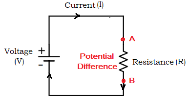
\( \mathrm{V = \dfrac{W}{Q}} \Rightarrow W = VQ \)
- If \( \mathrm{V} \) is constant, the energy transferred increases with the amount of charge that flows.
- If \( \mathrm{Q} \) is constant, the energy transferred increases with the voltage applied.
A higher potential difference means each coulomb of charge carries more energy — that’s why higher-voltage batteries can do more work for the same amount of charge.
Example
Find the energy transferred when a charge of \( \mathrm{15 \ C} \) passes through a potential difference of \( \mathrm{12 \ V.} \)
▶️ Answer / Explanation
Using \( \mathrm{W = VQ} \):
\( \mathrm{W = 12 \times 15 = 180 \ J.} \)
Therefore, 180 J of energy is transferred.
Example
How much energy is transferred by a \( \mathrm{230 \ V} \) electric kettle when \( \mathrm{10 \ C} \) of charge passes through it?
▶️ Answer / Explanation
Using \( \mathrm{W = VQ} \):
\( \mathrm{W = 230 \times 10 = 2300 \ J.} \)
Hence, the kettle transfers 2300 J (2.3 kJ) of electrical energy to heat.
Electrical Power Relationships
Electrical power (\( \mathrm{P} \)) is the rate at which energy is transferred or the rate at which work is done in an electrical circuit.
\( \mathrm{P = \dfrac{W}{t}} \)
From the definitions of current and potential difference:
- \( \mathrm{I = \dfrac{Q}{t}} \)
- \( \mathrm{V = \dfrac{W}{Q}} \)
Combining these gives: \( \mathrm{P = VI} \)
Using Ohm’s law (\( \mathrm{V = IR} \)), we can also write:
\( \mathrm{P = VI = I^2 R = \dfrac{V^2}{R}} \)
Each Equation Represents:
- \( \mathrm{P = VI} \): general definition of electrical power.
- \( \mathrm{P = I^2 R} \): power dissipated as heat in a resistor.
- \( \mathrm{P = \dfrac{V^2}{R}} \): power in terms of potential difference and resistance.
Power quantifies how fast electrical energy is converted into another form (heat, light, mechanical work, etc.). The higher the current or voltage, the greater the rate of energy transfer.
Example
A current of \( \mathrm{2.0 \ A} \) flows through a resistor connected to a \( \mathrm{12 \ V} \) battery. Find the power dissipated in the resistor.
▶️ Answer / Explanation
Using \( \mathrm{P = VI} \):
\( \mathrm{P = 12 \times 2.0 = 24 \ W.} \)
Therefore, the resistor dissipates 24 W of power.
Example
A 10 Ω resistor is connected across a 5 V supply. Calculate the power dissipated using both \( \mathrm{P = I^2 R} \) and \( \mathrm{P = \dfrac{V^2}{R}} \).
▶️ Answer / Explanation
Method 1: Find current using Ohm’s law: \( \mathrm{I = \dfrac{V}{R} = \dfrac{5}{10} = 0.5 \ A.} \)
Now, \( \mathrm{P = I^2 R = (0.5)^2 \times 10 = 2.5 \ W.} \)
Method 2: Using \( \mathrm{P = \dfrac{V^2}{R}} \): \( \mathrm{P = \dfrac{5^2}{10} = \dfrac{25}{10} = 2.5 \ W.} \)
Both methods give the same result — 2.5 W.