Circuit Components
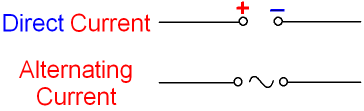
1. Cells, Batteries, Power Supplies
- Cell: Provides electrical energy (DC source).
- Battery: Two or more cells connected in series.
- Power Supply: Can provide constant or variable DC/AC.
- Symbol:

2. Switches
- Function: Opens or closes a circuit to control current flow.
- Symbol:
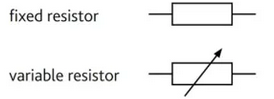
3. Fixed and Variable Resistors
- Fixed Resistor: Restricts current flow by a constant amount.
- Variable Resistor: Allows manual adjustment of resistance (used in dimmers/volume controls).
- Symbols:
4. Heater
- Function: Converts electrical energy to heat (e.g. kettles).
- Symbol:
5. Thermistor (NTC)
- Function: Resistance decreases as temperature increases.
- Use: Temperature sensors (e.g. fire alarms).
- Symbol:

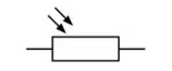
6. Light Dependent Resistor (LDR)
- Function: Resistance decreases as light intensity increases.
- Use: Automatic lights/streetlamps.
- Symbol:
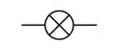
7. Lamp (Light bulb)
- Function: Converts electrical energy to light and heat.
- Symbol:
8. Motor
- Function: Converts electrical energy to mechanical motion.
- Symbol:
9. Bell
- Function: Converts electrical energy to sound.
- Symbol:

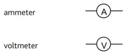
10. Ammeter & Voltmeter
- Ammeter: Measures current in amperes, placed in series.
- Voltmeter: Measures potential difference in volts, placed in parallel.
- Symbols:
11. Magnetising Coil
- Function: Creates a magnetic field when current passes.
- Use: Electromagnets in bells, relays, and motors.
- Symbols:
12. Transformer
- Function: Changes voltage (step-up or step-down) in AC circuits.
- Symbol:

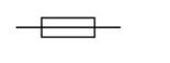
13. Fuse
- Function: Safety device that melts when current exceeds safe value.
- Symbol:
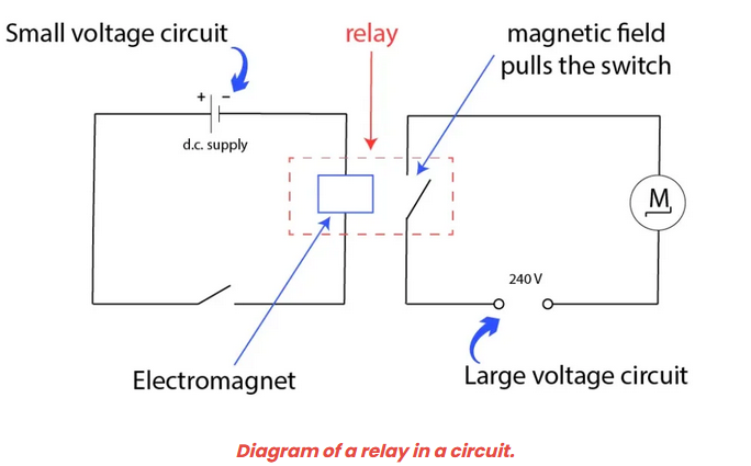
14. Relay
- Function: Electrically operated switch controlled by another current source (e.g., low voltage circuit triggering a high voltage one).
- Symbol:

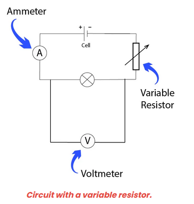
Example:
A student builds a circuit to control the brightness of a lamp using a variable resistor. The lamp and variable resistor are connected in series to a 6 V battery.
▶️ Answer/Explanation
Step 1: The circuit is a simple series connection:
Battery → Variable Resistor → Lamp → Battery
Step 2: As the resistance of the variable resistor increases, the current in the circuit decreases.
Step 3: Lower current results in reduced brightness of the lamp.
Final Answer: The variable resistor controls the brightness of the lamp by varying the current in the circuit.
\(\boxed{\text{Increasing resistance → dimmer lamp}}\)
Example:
A 5 V circuit is used to control a 230 V lamp using a relay. The 5 V circuit includes a switch and a coil connected to the relay. When the switch is closed, the 230 V lamp lights up.
▶️ Answer/Explanation
Step 1: The low-voltage circuit includes:
Battery → Switch → Relay Coil → Battery
Step 2: When the switch is closed, current flows through the relay coil, generating a magnetic field.
Step 3: The magnetic field closes the high-voltage contacts in the separate 230 V circuit, turning the lamp on.
Final Answer: The relay allows a low-voltage control circuit to switch on a high-voltage device safely.
\(\boxed{\text{Relay = electromagnetic switch}}\)
Diodes and Light-Emitting Diodes (LEDs)
1. Diodes – Behavior and Use
A diode allows current to flow in one direction only (forward direction), and blocks current in the reverse direction.
- Use: Rectification – converting AC to DC (half-wave rectifiers).
- Behavior:
- Current flows only when the anode is at a higher potential than the cathode.
- If reversed, no current flows.

2. Light-Emitting Diodes (LEDs) – Behavior and Use
An LED is a diode that emits light when current flows through it in the forward direction.
- Use: Indicators, display panels, digital clocks, etc.
- Behavior: Like a diode, but glows when conducting.
- Important: LEDs must be used with a series resistor to limit current and prevent damage.
Example:
Draw a simple circuit contains a diode and a lamp connected to a battery. The diode is forward-biased.
▶️ Answer/Explanation
Step 1: In forward bias, the anode of the diode is connected to the positive terminal and the cathode to the negative terminal.
Step 2: Current flows through the circuit, allowing the lamp to light up.
Step 3: If the diode is reversed, it becomes reverse-biased, blocking the current.
Final Answer: The lamp will only light up if the diode is forward-biased.
\(\boxed{\text{Forward bias → lamp on, Reverse bias → lamp off}}\)
