Electromagnetic Induction: Induced e.m.f. in a Conductor
An e.m.f. (electromotive force) is induced in a conductor when:
- A conductor moves through a magnetic field (cuts magnetic field lines) Or when the magnetic field linking with the conductor changes (e.g. field strength or orientation changes over time)
This is known as electromagnetic induction.
The conductor must either move across the field lines or experience a change in the magnetic field through it.
Conditions for Induced e.m.f.:
- The conductor must cut magnetic field lines (motion required).
- The magnetic field must vary with time (increasing/decreasing strength or moving magnet).
- No e.m.f. is induced if the conductor moves parallel to field lines (no cutting).
Example:
A straight metal rod is moved horizontally at constant speed through a uniform magnetic field pointing into the page. What happens to the rod?
▶️ Answer/Explanation
The rod cuts through magnetic field lines as it moves.
This causes an e.m.f. to be induced between its ends.
Free electrons inside the metal are pushed to one side due to the magnetic force (Lorentz force).
This charge separation leads to a potential difference across the rod.
If the rod is connected in a complete circuit, a current flows.
Direction of current: Can be found using Fleming’s Right-Hand Rule.
Let’s say:
- Rod moves to the right (Thumb → right)
- Magnetic field is into the page (First finger → into page)
- Then current flows upward in the rod (Second finger → up)
So, a current flows if the circuit is complete.
Concept: The movement of the rod through the magnetic field induces an e.m.f. (and current if a closed path exists).
Final Result: \(\boxed{\text{e.m.f. is induced due to motion across the magnetic field}}\)
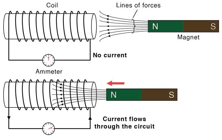
Experiment to Demonstrate Electromagnetic Induction
Aim: To show that moving a magnet through a coil induces an electromotive force (e.m.f.) and produces current.
Apparatus:
- Bar magnet
- Insulated copper wire wound into a coil
- Galvanometer (sensitive current meter)
- Connecting wires
Procedure:
- Connect the ends of the wire coil to the terminals of the galvanometer.
- Quickly push the north pole of the bar magnet into the coil and observe the galvanometer.
- Remove the magnet and observe again.
- Repeat the above using the south pole instead of the north pole.
Observations:
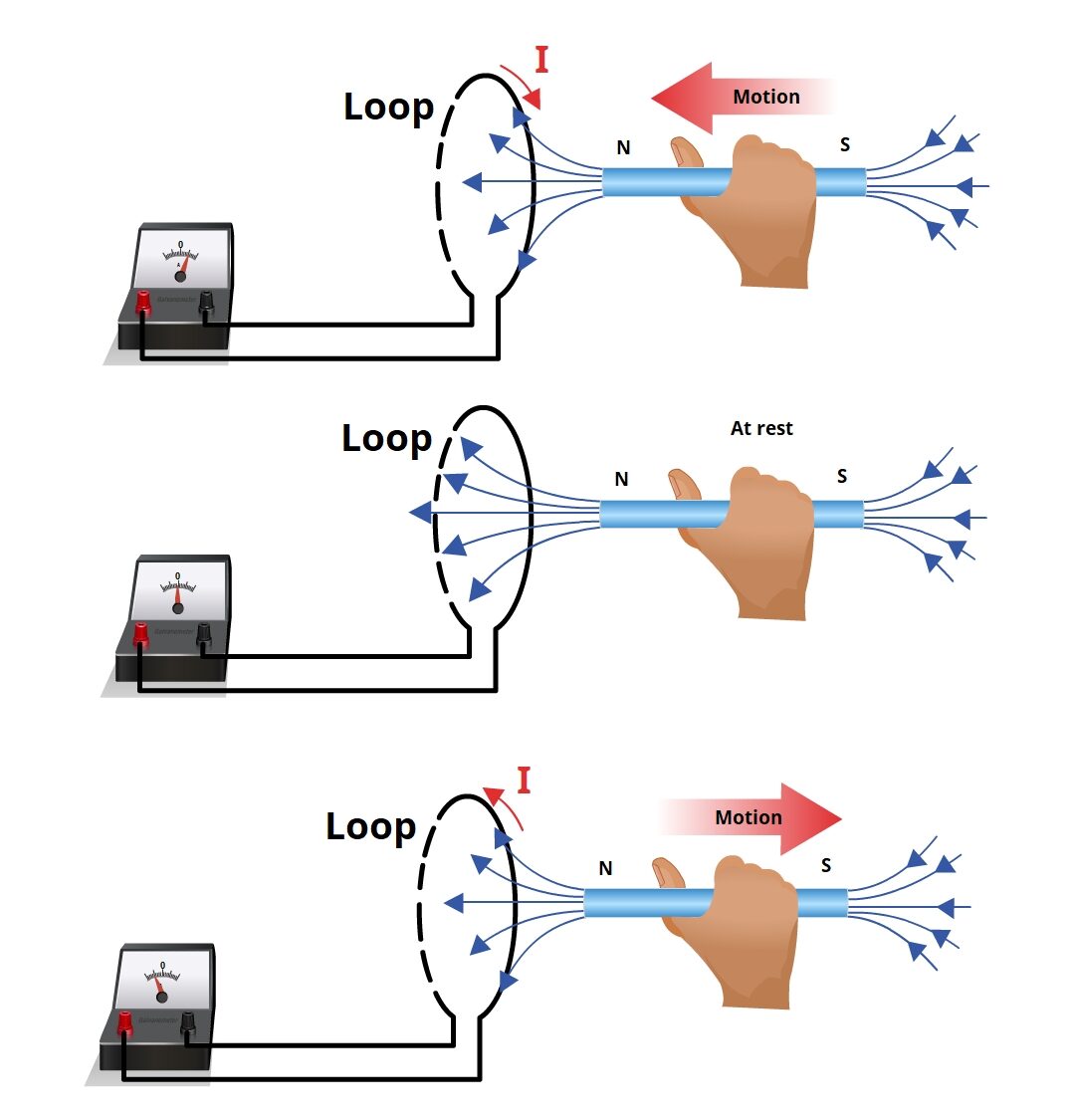
- The galvanometer needle deflects when the magnet is moved into the coil — indicating a current is induced.
- The needle deflects in the opposite direction when the magnet is pulled out of the coil.
- No deflection is observed when the magnet is held stationary inside the coil.
- The faster the magnet is moved, the greater the deflection (larger induced e.m.f.).
Conclusion:
- A changing magnetic field (caused by motion of the magnet) induces an e.m.f. in the coil.
- This supports Faraday’s Law of Electromagnetic Induction.
- The direction of the induced current depends on the direction of motion (in or out of the coil).
Induced e.m.f. – Key Concepts
Induced e.m.f.: An electromotive force (e.m.f.) is generated when a conductor experiences a changing magnetic field.This e.m.f. can cause a current to flow in a closed circuit. This phenomenon is called electromagnetic induction.
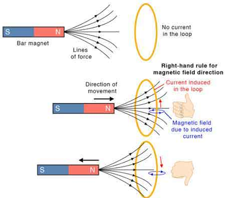
1. Direction of Induced e.m.f. (Lenz’s Law)
Lenz’s Law: The direction of the induced e.m.f. is always such that it opposes the change that caused it.
- This is a consequence of the conservation of energy — the induced current creates a magnetic field that resists the original motion.
Example: If a north pole of a magnet is moved toward a coil, the induced current in the coil flows in a direction that creates a magnetic north pole facing the incoming magnet (to repel it).
2. Relative Directions of Force, Magnetic Field, and Induced Current
When a conductor moves through a magnetic field, the direction of the induced current depends on:
- Direction of motion (force)
- Direction of magnetic field

Right-hand Rule (for generators):
- Thumb: Direction of motion (force)
- First finger: Magnetic field (from North to South)
- Second finger: Direction of induced current
3. Factors Affecting the Magnitude of the Induced e.m.f.
The induced e.m.f. becomes greater when:
- Magnetic field strength increases (stronger magnets used)
- Speed of motion of the conductor increases
- Number of turns in the coil increases
- Area of coil perpendicular to the magnetic field increases
- The rate of change of magnetic flux increases

Mathematical form (Faraday’s Law): \( \mathcal{E} = -N \frac{d\Phi}{dt} \)
- \( \mathcal{E} \): Induced e.m.f.
- \( N \): Number of turns of the coil
- \( \Phi \): Magnetic flux
- \( \frac{d\Phi}{dt} \): Rate of change of magnetic flux
Example:
A rectangular coil is moved quickly into a region with a strong magnetic field directed into the page. The coil is connected to a galvanometer. What will happen when the coil enters, stays, and leaves the field region? What factors would increase the galvanometer deflection?
▶️ Answer/Explanation
The magnetic field is perpendicular to the plane of the coil (into the page). As the coil enters the field, the magnetic flux through it increases — this change in flux induces an e.m.f.
When the coil enters the field, the induced current flows in a direction that tries to oppose the increasing flux (i.e., produces a field out of the page). The galvanometer will show a deflection in one direction.
Once the coil is completely inside the field and is not moving, there is no change in flux. Hence, no e.m.f. is induced and the galvanometer returns to zero.
As the coil leaves the field, the flux through it decreases. The induced current now flows in the opposite direction, attempting to oppose the loss of flux (i.e., tries to maintain flux into the page). The galvanometer deflects in the opposite direction.
Factors increasing induced e.m.f.
- Moving the coil faster
- Using a stronger magnetic field
- Increasing the number of turns in the coil
- Using a larger coil area
The galvanometer deflects one way as the coil enters the field, reads zero while the coil is stationary inside, and deflects the opposite way as the coil exits. Induced e.m.f. depends on speed, magnetic field strength, coil area, and number of turns.
Example:
A square coil of side \( 0.1 \, \text{m} \) and 200 turns is pulled completely out of a uniform magnetic field of strength \( 0.5 \, \text{T} \). The time taken to remove the coil is \( 0.2 \, \text{s} \). Calculate the magnitude of the average induced e.m.f. in the coil.
▶️ Answer/Explanation
The average induced e.m.f. is given by:
\( \mathcal{E} = \dfrac{N \Delta \Phi}{\Delta t} \)
Area of coil = \( A = (0.1)^2 = 0.01 \, \text{m}^2 \)
Initial flux through each turn: \( \Phi = B A = 0.5 \times 0.01 = 0.005 \, \text{Wb} \)
Final flux = 0 (coil removed from field)
Change in flux per turn: \( \Delta \Phi = 0.005 \, \text{Wb} \)
\( N = 200 \), \( \Delta t = 0.2 \, \text{s} \)
\( \mathcal{E} = \dfrac{200 \times 0.005}{0.2} = \dfrac{1}{0.2} = 5.0 \, \text{V} \)
The average induced e.m.f. is \( \boxed{5.0 \, \text{V}} \)