Electric Current, EMF, and Resistance in Series Circuits
Current is the same at every point in a series circuit:
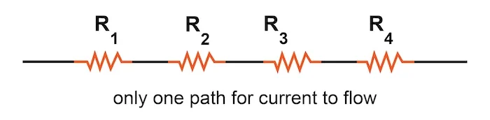
In a series circuit, there is only one path for current to flow. Hence, the current \( I \) is the same through all components, regardless of their resistances.
For example, if a series circuit contains a battery and three resistors, the current flowing through each resistor is equal.
Construct and use series circuits:
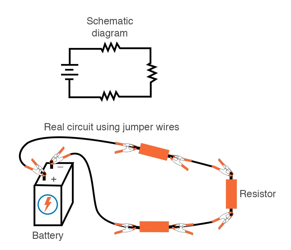
To build a series circuit:
- Connect the positive terminal of the battery to one end of the first component (e.g., resistor).
- Connect the other end of the first component to the next component, and so on.
- Finally, connect the last component back to the negative terminal of the battery.
Using a series circuit is useful when the same current is required through all devices (e.g., a string of fairy lights).
Combined electromotive force (emf) of several sources in series:
If multiple cells are connected in series, their voltages add:
\( \text{Total emf} = \varepsilon_1 + \varepsilon_2 + \varepsilon_3 + \ldots \)

Only applies if all sources are connected in the same direction. If one is reversed, its emf subtracts.
Combined resistance of two or more resistors in series:
Resistors in series add directly:
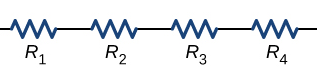
\( R_{\text{total}} = R_1 + R_2 + R_3 + \ldots \)
This increases the total resistance, reducing the current in the circuit.
Sum of the currents into a junction equals the sum out of the junction:
While this applies mainly to parallel circuits, it still holds that:

At any point in a series circuit, the current going in is the same as the current going out — because there are no branches.
Example:
Three resistors of resistance \( R_1 = 4\,\Omega \), \( R_2 = 6\,\Omega \), and \( R_3 = 10\,\Omega \) are connected in series with a 12 V battery. Calculate the total resistance, the current in the circuit, and the potential difference across each resistor.
▶️ Answer/Explanation
Step 1: Total resistance in series
\( R_{\text{total}} = R_1 + R_2 + R_3 = 4 + 6 + 10 = 20\,\Omega \)
Step 2: Total current using Ohm’s law
\( I = \frac{V}{R} = \frac{12}{20} = 0.6\,\text{A} \)
Step 3: Potential difference across each resistor
- \( V_1 = IR_1 = 0.6 \times 4 = 2.4\,\text{V} \)
- \( V_2 = IR_2 = 0.6 \times 6 = 3.6\,\text{V} \)
- \( V_3 = IR_3 = 0.6 \times 10 = 6.0\,\text{V} \)
Example:
A circuit consists of two batteries in series (1.5 V and 3 V) and two resistors in series: \( R_1 = 2\,\Omega \) and \( R_2 = 4\,\Omega \). Find the total emf, total resistance, and current in the circuit.
▶️ Answer/Explanation
Step 1: Total emf of batteries in series
\( \varepsilon_{\text{total}} = 1.5 + 3 = 4.5\,\text{V} \)
Step 2: Total resistance in series
\( R_{\text{total}} = R_1 + R_2 = 2 + 4 = 6\,\Omega \)
Step 3: Use Ohm’s law to find current
\( I = \frac{V}{R} = \frac{4.5}{6} = 0.75\,\text{A} \)
Example:
A series circuit has a power supply of 9 V and three identical resistors, each of resistance \( 3\,\Omega \). Find:
- Total resistance
- Total current
- Voltage across each resistor
▶️ Answer/Explanation
Step 1: Total resistance in series
Each resistor is \( 3\,\Omega \), so:
\( R_{\text{total}} = 3 + 3 + 3 = 9\,\Omega \)
Step 2: Use Ohm’s law to find total current
\( I = \frac{V}{R} = \frac{9}{9} = 1\,\text{A} \)
Step 3: Voltage across each resistor
Since all resistors are identical and in series, the voltage divides equally:
- \( V_1 = V_2 = V_3 = \frac{9\,\text{V}}{3} = 3\,\text{V} \)
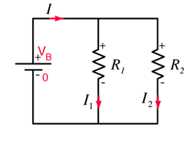
Constructing and Using Parallel Circuits
A parallel circuit has two or more branches connected across the same voltage source.
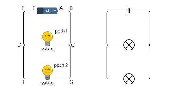
- Each component (e.g. lamp, resistor) in a branch has the same potential difference across it.
- Parallel circuits are constructed by placing components side-by-side so that current splits into different branches and then recombines.
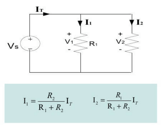
Current in Parallel Circuits

- The current from the source divides between the different branches of the circuit.
- The total current from the source is equal to the sum of the currents in each branch:
\( I_{\text{total}} = I_1 + I_2 + I_3 + \ldots \)
Potential Difference in Parallel Circuits

- All branches in a parallel circuit have the same potential difference (voltage) as the source.
- This means each lamp or component in parallel receives the full supply voltage.
Resistance in Parallel Circuits
- The combined or equivalent resistance \( R_{\text{total}} \) of two or more resistors in parallel is less than the resistance of the smallest individual resistor.
- This is because adding more paths allows more current to flow, reducing the total resistance.
The formula for two resistors in parallel:
\( \frac{1}{R_{\text{total}}} = \frac{1}{R_1} + \frac{1}{R_2} \)
For three resistors:
\( \frac{1}{R_{\text{total}}} = \frac{1}{R_1} + \frac{1}{R_2} + \frac{1}{R_3} \)
Advantages of Connecting Lamps in Parallel
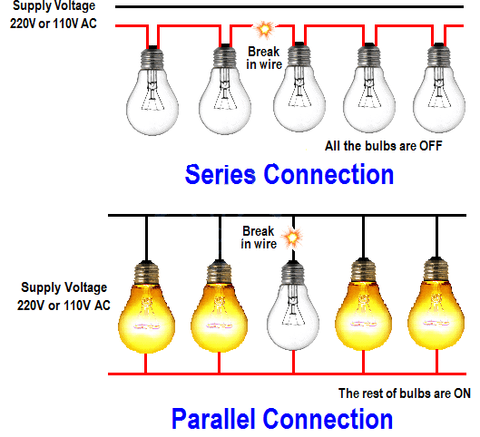
- Each lamp receives the full supply voltage, so all glow at full brightness.
- If one lamp fails, the others continue to operate (unlike in series).
- Lamps can be controlled independently if switches are added to each branch.
Example :
A 12 V battery is connected to two identical lamps in parallel. Each lamp has a resistance of 6 Ω. Find:
- (a) the current through each lamp
- (b) the total current from the battery
▶️ Answer/Explanation
Each lamp is directly across the 12 V battery, so:
\( I = \frac{V}{R} = \frac{12}{6} = 2 \ \text{A} \)
So, current through each lamp = 2 A.
Total current from the battery = sum of branch currents:
\( I_{\text{total}} = 2 \ \text{A} + 2 \ \text{A} = \boxed{4 \ \text{A}} \)
Example :
Two resistors of 4 Ω and 12 Ω are connected in parallel. Calculate the total resistance of the combination.
▶️ Answer/Explanation
Use the parallel resistance formula:
\( \frac{1}{R_{\text{total}}} = \frac{1}{4} + \frac{1}{12} = \frac{3 + 1}{12} = \frac{4}{12} = \frac{1}{3} \)
Now invert to find total resistance:
\( R_{\text{total}} = \frac{1}{\frac{1}{3}} = \boxed{3 \ \Omega} \)
Example :
A 9 V supply is connected to three different resistors (10 Ω, 20 Ω, and 30 Ω) in parallel. What is the voltage across each resistor?
▶️ Answer/Explanation
In a parallel circuit, each branch is directly across the voltage supply.
So, voltage across each resistor = \(\boxed{9 \ \text{V}}\)
(a) Conservation of Current at a Junction (Parallel Circuits)
At any junction in a parallel circuit, the total current flowing into the junction is equal to the total current flowing out.

This follows from the conservation of charge. No charge is lost or gained at a junction — it just splits between branches.
If current \( I_{\text{in}} \) enters a junction and splits into branches with currents \( I_1, I_2, I_3 \), then:
\( I_{\text{in}} = I_1 + I_2 + I_3 + \cdots \)
(b) Potential Difference in Series Circuits
In a series circuit, the total potential difference (voltage) across the power source is shared among the components.
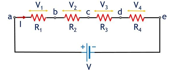
If several resistors \( R_1, R_2, R_3 \) are connected in series across a battery, then the total voltage is:
\( V_{\text{total}} = V_1 + V_2 + V_3 \)
Where \( V_1, V_2, V_3 \) are the potential differences across each component.
(c) Potential Difference Across Parallel Branches
In a parallel arrangement of resistors or components, the potential difference (voltage) across each branch is the same and is equal to the potential difference across the entire parallel combination.
![]()
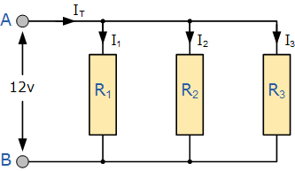
If a 12 V battery is connected across two or more parallel branches, then:
\( V_{\text{total}} = V_1 = V_2 = V_3 = \cdots \)
This is why bulbs in parallel all glow equally bright if they are identical — they each receive the full supply voltage.
Example
A current of \(6\ \text{A}\) flows into a junction. It splits into two branches: one branch carries \(2.3\ \text{A}\). What is the current in the second branch?
▶️ Answer/Explanation
We use the conservation of current at a junction:
\( I_{\text{in}} = I_1 + I_2 \)
\( 6.0 = 2.3 + I_2 \)
\( I_2 = 6.0 – 2.3 = 3.7\ \text{A} \)
\(\boxed{I_2 = 3.7\ \text{A}}\)
Example
Two resistors \( R_1 = 5\ \Omega \) and \( R_2 = 10\ \Omega \) are connected in series across a \(9\ \text{V}\) battery. What is the potential difference across each resistor?
▶️ Answer/Explanation
First, calculate total resistance:
\( R_{\text{total}} = R_1 + R_2 = 5 + 10 = 15\ \Omega \)
Now find current in the circuit using \( I = V / R \):
\( I = 9 / 15 = 0.6\ \text{A} \)
Now apply Ohm’s law to each resistor:
\( V_1 = I \times R_1 = 0.6 \times 5 = 3.0\ \text{V} \)
\( V_2 = I \times R_2 = 0.6 \times 10 = 6.0\ \text{V} \)
Check: \( V_1 + V_2 = 3.0 + 6.0 = 9.0\ \text{V} \)
Example
A \(12\ \text{V}\) battery is connected to two resistors in parallel: \( R_1 = 8\ \Omega \), \( R_2 = 4\ \Omega \). What is the voltage across each resistor?
▶️ Answer/Explanation
In a parallel circuit, the voltage across each branch is equal to the total voltage supplied by the battery:
\(\boxed{V_1 = V_2 = 12\ \text{V}}\)
This is true regardless of the individual resistances.
Comparison table:
| Features |
Series Circuit |
Parallel Circuit |
|---|---|---|
| Connection of Components | Connected one after another in a single loop | Connected on separate branches |
| Current | Same at every point: \( I = I_1 = I_2 = \dots \) | Splits across branches: \( I = I_1 + I_2 + \dots \) |
| Voltage (Potential Difference) | Shared between components: \( V = V_1 + V_2 + \dots \) | Same across all branches: \( V = V_1 = V_2 = \dots \) |
| Resistance | Increases with more resistors: \( R = R_1 + R_2 + \dots \) | Decreases with more resistors: \( \frac{1}{R} = \frac{1}{R_1} + \frac{1}{R_2} + \dots \) |
| If One Component Fails | Whole circuit stops working | Other branches continue to work |
| Brightness of Identical Lamps | Dimmer as more lamps are added | Same brightness in each branch |
| Fault Detection | Difficult – entire circuit is affected | Easier – each branch can be tested independently |
| Use in Homes | Rare – not practical for domestic circuits | Common – used for lighting and sockets |
| Total Power Supplied | Depends on total resistance and current: \( P = IV \) | Higher total current drawn: \( P = I_1V + I_2V + \dots \) |

