Thin Converging and Diverging Lenses on Parallel Light
1. Converging Lens (Convex Lens):
A converging lens is thicker in the middle than at the edges.
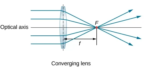
- When a parallel beam of light passes through a converging lens:
- The rays are bent inward (refracted toward the axis).
- They meet (converge) at a point called the principal focus (F).
- The distance from the lens to the principal focus is the focal length (f).
Key Result: A parallel beam of light is focused to a point.
2. Diverging Lens (Concave Lens):
A diverging lens is thinner in the middle than at the edges.

- When a parallel beam of light passes through a diverging lens:
- The rays are bent outward (refracted away from the axis).
- They appear to diverge from a point behind the lens – the principal focus (virtual focus).
- The focal length is measured from the lens to this virtual focus.
Key Result: A parallel beam of light appears to diverge from a point.
Example :
Parallel rays of light are incident on two lenses – one convex and one concave. What happens to the rays after passing through each lens?
▶️ Answer/Explanation
The convex (converging) lens refracts the rays to meet at a point on the principal axis – the focal point. The concave (diverging) lens causes the rays to spread out as if they are coming from a virtual focal point on the same side as the object.
Key Terms in Lenses and Refraction
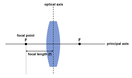
Principal Axis:
- A straight horizontal line that passes through the center of the lens and is perpendicular to its surface.
- It serves as the reference line for locating the focal point and drawing ray diagrams.
Principal Focus (Focal Point):
The point on the principal axis where a beam of light rays parallel to the axis either:
- Converges (for a converging lens), or
- Appears to diverge from (for a diverging lens).
Focal Length (f):
- The distance between the center of the lens and the principal focus.
- It is usually measured in centimetres (cm) or metres (m).
Note: Both converging and diverging lenses have two focal points — one on each side of the lens — but ray diagrams typically focus on the side the light enters.
Example :
In a ray diagram, the object is placed at a distance from a converging lens. Define the principal focus and state where it is located for this lens.
▶️Answer/Explanation
The principal focus is the point where rays parallel to the principal axis converge after passing through a converging lens. It lies on the opposite side of the lens from the object, at a distance equal to the focal length.
Ray Diagram for Real Image Formation by a Converging Lens
Case: Object placed beyond the focal point (F), e.g. between 2F and ∞.
How to Draw the Ray Diagram:
- Draw the principal axis a straight horizontal line through the center of the lens.
- Place the converging lens in the center, with a vertical line representing the lens.
- Mark the two focal points (F) on either side of the lens, and 2F (twice the focal length).
- Place the object upright, beyond F, on the left of the lens.

Draw the 2 main rays:
- Ray 1: Draw a ray parallel to the principal axis from the top of the object – it refracts through the focal point (F) on the other side.
- Ray 2: Draw a ray through the center of the lens – it goes straight without bending.
Where the two refracted rays meet on the right side is the location of the real image.
Characteristics of the Image:
- Real – rays actually meet at the image location
- Inverted – upside down compared to the object
- Can be smaller, same size, or larger depending on object distance
- Formed on the opposite side of the lens from the object
- Can be projected onto a screen
Example :
A student places an object 8 cm from a converging lens of focal length 10 cm. Will the lens form a real or virtual image? Justify your answer.
▶️ Answer/Explanation
The object is placed within the focal length (since 8 cm < 10 cm), so the lens will form a virtual, upright, and magnified image on the same side of the lens as the object.
Ray Diagram for Virtual Image Formation by a Converging Lens
Case: The object is placed between the lens and its focal point (F).
How to Draw the Ray Diagram:
- Draw the principal axis (a straight horizontal line through the center of the lens).
- Draw the converging lens as a vertical line in the center.
- Mark the focal point (F) and 2F on both sides of the lens.
- Place the object upright between the lens and the focal point on the left side.

Draw the 2 main rays:
- Ray 1: From the top of the object, draw a ray parallel to the principal axis. When it reaches the lens, refract it away through the focal point on the other side of the lens.
- Ray 2: Draw a ray going toward the center of the lens – it passes through undeviated.
Now extend the refracted rays backward with dotted lines on the left side of the lens. They appear to meet at a point — this is where the virtual image forms.
Characteristics of the Image:
- Virtual – rays only appear to meet; cannot be projected
- Upright – same orientation as the object
- Larger than the object (magnified)
- Formed on the same side of the lens as the object

Example :
An object is placed 5 cm from a convex lens with a focal length of 10 cm. Using ray diagram principles, determine the nature and position of the image formed.
▶️ Answer/Explanation
Since the object is placed closer than the focal length (5 cm < 10 cm), the convex lens produces a virtual, upright, and magnified image.
In the ray diagram:
- One ray travels parallel to the principal axis, then refracts and passes through the focal point on the other side.
- Another ray travels straight toward the center of the lens and passes undeviated.
- These rays appear to diverge, so their backward extensions meet to form a virtual image on the same side as the object.

The image is upright, virtual, and larger than the object.
Describing Image Characteristics Using Lenses
When an image is formed by a lens, we describe it using the following terms:
Size:
- Enlarged – image is bigger than the object
- Same size – image is equal in size to the object
- Diminished – image is smaller than the object
Orientation:
- Upright – image has the same orientation as the object (not flipped)
- Inverted – image is upside-down compared to the object
Type:
- Real – light rays actually meet; image can be projected on a screen

Use of a Single Converging Lens as a Magnifying Glass
A magnifying glass is a single convex (converging) lens.

- The object is placed closer to the lens than its focal point (F).
- This causes the lens to form a virtual, upright, and enlarged image.
- The image appears on the same side of the lens as the object.
Why it’s useful: This allows the human eye to see small details more clearly because the angular size of the object is increased.
Virtual Images
A virtual image is formed when the light rays that emerge from a lens or mirror appear to come from a common point, but they do not actually meet.
- The rays are diverging when they leave the lens or mirror.
- The brain assumes light travels in straight lines, so it extrapolates the rays backward to a point behind the lens or mirror where they appear to meet.
- This point is where the virtual image is located.
Key Characteristics of Virtual Images:
- They are formed by the backward extension of diverging rays.
- They cannot be projected onto a screen because light doesn’t actually come from the image location.
- They are always upright (compared to the object).
- They can be enlarged or diminished depending on the setup.
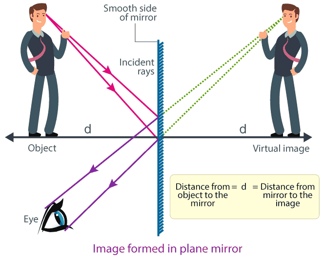
Examples of Virtual Images:
- The image seen in a plane mirror
- The magnified image seen through a magnifying glass
- The image formed by a diverging lens
Example :
In an experiment, an object is placed 30 cm from a convex lens of focal length 15 cm. What are the characteristics of the image?
▶️ Answer/Explanation
Since the object is at 2F (30 cm = 2 × 15 cm), the image is real, inverted, and same size as the object. It forms at 2F on the opposite side of the lens.
Use of Lenses to Correct Vision Defects
1. Long-sightedness (Hyperopia):
People with long-sightedness can see distant objects clearly but cannot focus on nearby objects.

- This happens because the eyeball is too short or the lens is too weak, so light rays focus behind the retina.
- A converging (convex) lens is used in glasses to correct this.
- The converging lens bends incoming light rays inward before they enter the eye, helping them focus directly on the retina.
2. Short-sightedness (Myopia):
People with short-sightedness can see nearby objects clearly but cannot focus on distant objects.

- This happens because the eyeball is too long or the lens is too strong, so light rays focus in front of the retina.
- A diverging (concave) lens is used in glasses to correct this.
- The diverging lens spreads out incoming light rays before they enter the eye, so they focus correctly on the retina.
Example:
A child cannot clearly see the whiteboard at the front of the classroom, but can read a book clearly at close distance. What vision defect is present, and what lens corrects it?
▶️ Answer/Explanation
This is short-sightedness (myopia). The image of distant objects forms in front of the retina. It is corrected using a diverging (concave) lens.