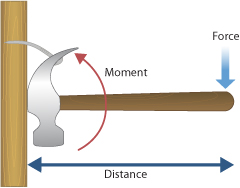
Moment of a Force
The moment of a force describes the turning effect of a force about a pivot or turning point.
Moments are important in situations involving levers, spanners, doors, see-saws, and balance.
Pivot
The pivot is the point about which an object turns.

- Also called the turning point.
- Examples include door hinges and the centre of a see-saw.
Key Relationship
The relationship between the moment of a force and its perpendicular distance from the pivot is:

\( \mathrm{moment = force \times perpendicular\ distance\ from\ the\ pivot} \)
\( \mathrm{M = F \times d} \)
- \( \mathrm{M} \) = moment (newton metre, Nm)
- \( \mathrm{F} \) = force (N)
- \( \mathrm{d} \) = perpendicular distance from pivot (m)
Perpendicular Distance
The perpendicular distance is the shortest distance from the pivot to the line of action of the force.
- Only the perpendicular distance is used in calculations.
- A larger perpendicular distance produces a larger moment.
Direction of Rotation
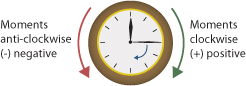
- A force can produce a clockwise moment.
- Or an anticlockwise moment.
- The direction depends on how the force acts relative to the pivot.
Increasing the Moment
- Increase the size of the force.
- Increase the perpendicular distance from the pivot.
This is why a longer spanner makes turning a nut easier.
Key Idea
- Moments measure turning effects.
- Perpendicular distance is essential.
- Moments depend on force and distance.
Important Points to Remember
- Moment is measured in newton metres (Nm).
- Distance must be perpendicular to the force.
- Forces acting through the pivot produce no moment.
Example
A force of \( \mathrm{10\ N} \) acts at a perpendicular distance of \( \mathrm{0.30\ m} \) from a pivot. Calculate the moment of the force.
▶️ Answer / Explanation
Use: \( \mathrm{M = F \times d} \)
\( \mathrm{M = 10 \times 0.30} \)
\( \mathrm{M = 3.0\ Nm} \)
Example
A door is pushed with a force of \( \mathrm{15\ N} \). The perpendicular distance from the hinge is \( \mathrm{0.80\ m} \). Calculate the moment produced about the hinge.
▶️ Answer / Explanation
Use: \( \mathrm{M = F \times d} \)
\( \mathrm{M = 15 \times 0.80} \)
\( \mathrm{M = 12\ Nm} \)
Principle of Moments (Parallel Forces in One Plane)
The principle of moments is used to analyse systems where several parallel forces act on an object in the same plane. It helps determine whether an object will rotate or remain in equilibrium.
This principle is commonly applied to beams, see-saws, balances, and bridges.
Parallel Forces in One Plane
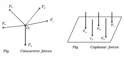
- Parallel forces act in the same or opposite directions.
- They lie in the same flat surface (one plane).
- Forces may act at different distances from a pivot.
Pivot (Turning Point)
The pivot is the point about which the object may rotate.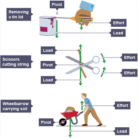
- Can be a support or hinge.
- Moments are calculated about the pivot.
Moment of a Force
The moment of a force is given by:
\( \mathrm{moment = force \times perpendicular\ distance\ from\ pivot} \)
\( \mathrm{M = F \times d} \)
- \( \mathrm{M} \) = moment (Nm)
- \( \mathrm{F} \) = force (N)
- \( \mathrm{d} \) = perpendicular distance (m)
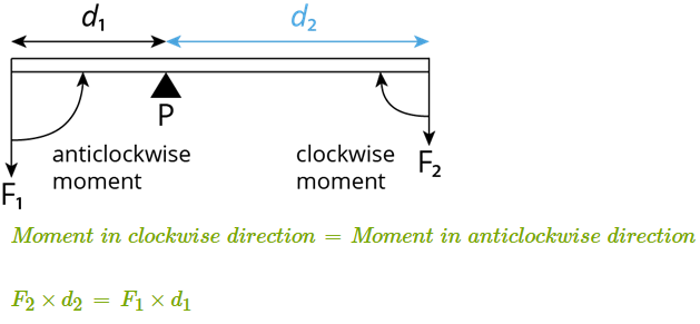
Principle of Moments
For a system in equilibrium:

\( \mathrm{total\ clockwise\ moments = total\ anticlockwise\ moments} \)
- The object does not rotate.
- Forces and distances must balance.
Applying the Principle
- Choose a convenient pivot.
- Identify clockwise and anticlockwise moments.
- Calculate each moment using \( \mathrm{M = Fd} \).
- Set clockwise moments equal to anticlockwise moments.
Vertical Force Balance
In equilibrium, vertical forces must also balance:
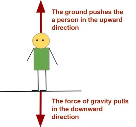
\( \mathrm{total\ upward\ forces = total\ downward\ forces} \)
Key Idea
- Moments determine turning effects.
- Balanced moments mean no rotation.
- Parallel forces can be analysed using moments.
Important Points to Remember
- Always use perpendicular distances.
- Moments depend on both force and distance.
- Choose the pivot to simplify calculations.
Example
A see-saw is balanced about a central pivot. A force of \( \mathrm{200\ N} \) acts \( \mathrm{1.5\ m} \) to the left of the pivot. Calculate the force needed \( \mathrm{1.0\ m} \) to the right of the pivot to keep it balanced.
▶️ Answer / Explanation
Left moment:
\( \mathrm{M = 200 \times 1.5 = 300\ Nm} \)
Right moment:
\( \mathrm{M = F \times 1.0} \)
Using the principle of moments:
\( \mathrm{300 = F \times 1.0} \)
\( \mathrm{F = 300\ N} \)
Example
A light beam is supported at one end and balanced horizontally. A \( \mathrm{100\ N} \) force acts \( \mathrm{0.4\ m} \) from the pivot. A second force acts \( \mathrm{0.8\ m} \) on the opposite side. Calculate the size of the second force.
▶️ Answer / Explanation
Moment on one side:
\( \mathrm{M = 100 \times 0.4 = 40\ Nm} \)
Opposite moment:
\( \mathrm{M = F \times 0.8} \)
Using the principle of moments:
\( \mathrm{40 = F \times 0.8} \)
\( \mathrm{F = 50\ N} \)
Upward Forces on a Supported Beam
A light beam supported at its ends experiences upward forces (reaction forces) at each support. When a heavy object is placed on the beam, the sizes of these upward forces depend on the position of the object.
This situation is analysed using the principle of moments.
Forces Acting on the Beam

- The weight of the object acting downward.
- An upward force at the left support.
- An upward force at the right support.
The beam is described as light, meaning its own weight is negligible.
Principle of Moments
For a beam in equilibrium:
\( \mathrm{total\ clockwise\ moments = total\ anticlockwise\ moments} \)
This principle is used to calculate the upward forces at the supports.
How Position Affects Upward Forces
- If the object is placed closer to one support, that support provides a larger upward force.
- The support further away provides a smaller upward force.
- If the object is in the centre, the upward forces are equal.
The total upward force is always equal to the weight of the object.
Key Relationships
- Vertical equilibrium: \( \mathrm{upward\ forces = downward\ forces} \)
- Moment: \( \mathrm{moment = force \times perpendicular\ distance} \)
Understanding the Beam System
- The beam does not rotate because moments are balanced.
- Changing the position of the object changes the moments.
- The support closer to the load must supply a larger force.
Key Idea
- Upward forces depend on object position.
- Moments must balance for equilibrium.
- The sum of upward forces equals the weight.
Important Points to Remember
- The beam is assumed to be light.
- Distances are measured from the pivot or support.
- Use perpendicular distances when calculating moments.
Example
A light beam of length \( \mathrm{4.0\ m} \) is supported at both ends. A \( \mathrm{200\ N} \) weight is placed exactly at the centre of the beam. Calculate the upward force at each support.
▶️ Answer / Explanation
The load is in the centre, so the forces are equal.
Total upward force = \( \mathrm{200\ N} \)
\( \mathrm{Upward\ force\ at\ each\ support = 100\ N} \)
Example
A light beam is \( \mathrm{5.0\ m} \) long and supported at both ends. A \( \mathrm{300\ N} \) weight is placed \( \mathrm{1.0\ m} \) from the left support. Calculate the upward force at the right support.
▶️ Answer / Explanation
Take moments about the left support.
Clockwise moment = \( \mathrm{300 \times 1.0} \)
Anticlockwise moment = \( \mathrm{F \times 5.0} \)
Using the principle of moments:
\( \mathrm{300 \times 1.0 = F \times 5.0} \)
\( \mathrm{F = 60\ N} \)
The upward force at the right support is \( \mathrm{60\ N} \).