Current–Voltage (I–V) Characteristics of Components
The relationship between current and voltage is different for different electrical components. These relationships are shown using current–voltage (I–V) graphs.
Studying I–V characteristics helps us understand how components behave in electrical circuits.
Key Relationship
For components that obey Ohm’s law:
\( \mathrm{V = IR} \)
or
\( \mathrm{I = \dfrac{V}{R}} \)
- \( \mathrm{V} \) = voltage (V)
- \( \mathrm{I} \) = current (A)
- \( \mathrm{R} \) = resistance (Ω)
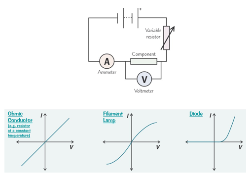
1. Wires (Ohmic Conductors)
Wires are examples of ohmic conductors.
- Current is directly proportional to voltage.
- Resistance remains constant.
- Obeys Ohm’s law.
I–V graph:

- Straight line through the origin.
- Constant gradient.
2. Fixed Resistors
Fixed resistors also obey Ohm’s law.
- Current increases linearly with voltage.
- Resistance is constant.
- Used to control current.
I–V graph:
- Straight line through the origin.
3. Metal Filament Lamps
Metal filament lamps are non-ohmic devices.
- As current increases, filament temperature increases.
- Resistance increases with temperature.
- Current increases less rapidly at higher voltages.
I–V graph:

- Curved line.
- Gradient decreases as voltage increases.
4. Diodes
A diode allows current to flow in one direction only.
- Very small current for low forward voltage.
- Large current after a threshold voltage.
- No current in reverse direction.
I–V graph:

- Sharp rise in current in forward direction.
- Zero current in reverse direction.
Comparing I–V Characteristics
- Wire/resistor: straight line (ohmic).
- Filament lamp: curved due to heating.
- Diode: one-directional current.
Experimental Investigation of I–V Characteristics
Aim
To investigate how current varies with voltage for different electrical components.
Apparatus
- Power supply (low voltage)
- Ammeter
- Voltmeter
- Variable resistor
- Connecting wires
- Component under test (wire, resistor, lamp, diode)
Method
- Connect the component in series with an ammeter.

- Connect a voltmeter across the component.
- Use a variable resistor to change the voltage.
- Record current and voltage readings.
- Repeat for a range of voltages.
- Reverse polarity for diode testing.
Results and Graphs
- Plot current (I) on the y-axis.
- Plot voltage (V) on the x-axis.
- Analyse the shape of the graph.
Safety and Accuracy
- Switch off supply between readings.
- Use low voltages to prevent overheating.
- Take readings quickly for filament lamps.
Key Idea
- Different components have different I–V characteristics.
- Ohmic components obey Ohm’s law.
- Graphs reveal component behaviour.
Important Points to Remember
- Current–voltage graphs must start at the origin (except diodes).
- Temperature affects resistance.
- Always label axes with units.
Example
State which component obeys Ohm’s law and describe its I–V graph.
▶️ Answer / Explanation
A fixed resistor (or wire) obeys Ohm’s law.
Its I–V graph is a straight line through the origin.
Example
Explain why the I–V graph for a filament lamp is curved.
▶️ Answer / Explanation
As current increases, the filament heats up.
The resistance increases, so current increases more slowly.