
Edexcel iGCSE Physics (4PH1) 2.2 Mains Electricity Exam Style Question Paper 1B - New Syllabus
Question
This is a simplified diagram of the electrical wiring in a house.
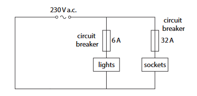
The house supply is \(230\,\mathrm{V}\) a.c. The lighting circuit has a \(6\,\mathrm{A}\) circuit breaker and the socket circuit has a \(32\,\mathrm{A}\) circuit breaker.
(a) A current larger than \(32\,\mathrm{A}\) flows in the sockets.
Describe how having the circuit breaker in series with the sockets protects the house. (2 marks)
________________________________________________________________________________________________
(b) A student suggests that fuses could be used instead of the circuit breakers.
Give two disadvantages of using fuses instead of circuit breakers. (2 marks)
1. ________________________________________________________________________________________________
2. ________________________________________________________________________________________________
(c) Explain why the wiring in the house includes an earth wire. (2 marks)
________________________________________________________________________________________________
________________________________________________________________________________________________
Syllabus Topic Codes (Edexcel International GCSE Physics 4PH1):
• 2.2: Domestic electrical safety, including circuit breakers, fuses and earth wires — part (b)
• 2.2: Domestic electrical safety, including circuit breakers, fuses and earth wires — part (c)
▶️ Answer/Explanation and Mark Scheme
(a) Circuit breaker [2 marks]
- If the current becomes too high, the circuit breaker trips and opens the circuit.
- This stops the current and prevents overheating and possible fire.
(b) Disadvantages of fuses [2 marks]
- A fuse cannot be reset and must be replaced after it melts.
- A fuse is generally slower to break the circuit than a circuit breaker.
(c) Earth wire [2 marks]
- In the event of a fault, such as a live wire touching the metal case of an appliance, current flows through the earth wire.
- The large current causes the circuit breaker to trip, disconnecting the supply and reducing the risk of electric shock.
Total: \(6\) marks
Question
Fluorescent tube lamps can be used in schools and office buildings for lighting.
The photograph shows an engineer installing a fluorescent tube lamp.
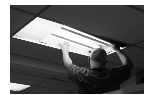
Diagram 1 shows a simplified view of the components of a fluorescent tube lamp.
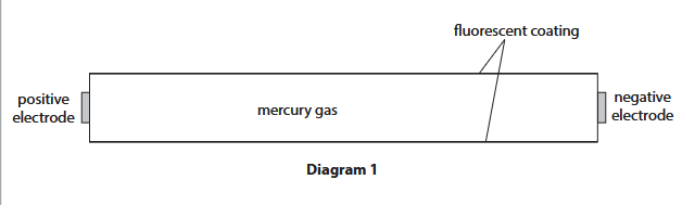
(a) When the lamp is on, a large voltage is applied between the positive electrode and the negative electrode.
(i) State what is meant by the term voltage. (1)
(ii) The large voltage causes electrons to accelerate from the negative electrode towards the positive electrode.
An electron gains \(1.0\times10^{-16}\,\mathrm{J}\) of energy when it accelerates between the electrodes.
Show that the voltage between the electrodes is about \(600\,\mathrm{V}\).
[magnitude of electron charge \(=1.6\times10^{-19}\,\mathrm{C}\)] (3)
(iii) The electron gains \(1.0\times10^{-16}\,\mathrm{J}\) of energy in its kinetic store when it accelerates from the negative electrode to the positive electrode.
Calculate the speed of an electron when it reaches the positive electrode.
Assume the electron is initially at rest.
[electron mass \(=9.1\times10^{-31}\,\mathrm{kg}\)] (4)
(b) When the electrons accelerate between the electrodes, they collide with mercury atoms.
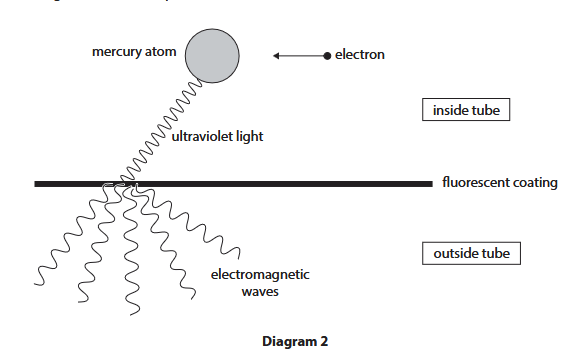
Energy is transferred to the mercury atoms during the collisions. This causes the mercury atoms to emit ultraviolet light.
Atoms in the fluorescent coating absorb this ultraviolet light, which is then re-emitted as light from a different part of the electromagnetic spectrum.
Diagram 2 shows this process.
(i) Suggest why the tube must have a fluorescent coating for the lamp to operate effectively. (2)
(ii) Explain why the fluorescent tube lamp is dangerous if the fluorescent coating becomes damaged. (2)
Syllabus Topic Codes (Edexcel International GCSE Physics 4PH1):
• 4.4–4.5: Kinetic energy and energy transfers — part (a)(iii)
• 3.12–3.14: Electromagnetic waves and the electromagnetic spectrum — parts (b)(i) and (b)(ii)
• 7.4–7.5 and 7.15–7.16: Ionising radiation and associated hazards — part (b)(ii)
▶️ Answer/Explanation
(a)(i) Meaning of voltage [1 mark]
Voltage is the energy transferred per unit charge.
The relationship is:
\(V=\dfrac{E}{Q}\)
where \(V\) is voltage, \(E\) is energy transferred and \(Q\) is charge.
(a)(ii) Voltage between the electrodes [3 marks]
1. Use the electrical energy equation:
\(E=QV\)
2. Rearrange for voltage:
\(V=\dfrac{E}{Q}\)
3. Substitute the values:
\(V=\dfrac{1.0\times10^{-16}}{1.6\times10^{-19}}\)
\(V=625\,\mathrm{V}\)
Therefore, the voltage is about \(600\,\mathrm{V}\).
Final Answer: \( \boxed{625\,\mathrm{V}\approx600\,\mathrm{V}} \)
(a)(iii) Speed of the electron [4 marks]
The electron starts from rest, so its initial kinetic energy is zero. The energy gained becomes kinetic energy.
1. Use the kinetic energy equation:
\(E_{\mathrm{k}}=\dfrac{1}{2}mv^2\)
2. Rearrange for \(v\):
\(v^2=\dfrac{2E_{\mathrm{k}}}{m}\)
\(v=\sqrt{\dfrac{2E_{\mathrm{k}}}{m}}\)
3. Substitute the values:
\(v=\sqrt{\dfrac{2(1.0\times10^{-16})}{9.1\times10^{-31}}}\)
\(v\approx1.48\times10^7\,\mathrm{m\,s^{-1}}\)
Final Answer: \( \boxed{1.5\times10^7\,\mathrm{m\,s^{-1}}} \)
(b)(i) Function of the fluorescent coating [2 marks]
- Humans cannot see ultraviolet radiation.
- The fluorescent coating absorbs the ultraviolet radiation and emits visible light, which can be seen by humans.
Therefore, the coating converts the ultraviolet radiation produced by the mercury atoms into visible light, making the lamp useful for lighting.
(b)(ii) Danger if the coating is damaged [2 marks]
- If the coating is damaged, ultraviolet radiation could escape from the tube.
- Ultraviolet radiation is ionising radiation and can cause harmful effects such as skin damage, burns or an increased risk of cancer.
Mercury vapour is also harmful if it escapes from the damaged tube.
Final Answer: A damaged coating may allow ultraviolet radiation to escape. UV radiation can damage living cells and is harmful to people, while escaped mercury vapour is also toxic.
Question
The photograph shows an electric heater connected to the mains electricity supply.

The circuit the heater is connected to is fitted with a circuit breaker, which breaks the circuit if the current gets too high.
(a) Give an advantage of using a circuit breaker instead of using a fuse.
(b) The voltage of the mains electricity supply is \(230\,\mathrm{V}\).
(i) State the formula linking power, current and voltage.
(ii) The normal operating current of the heater is \(11\,\mathrm{A}\). Calculate the input power to the heater for this current. Give your answer in \(\mathrm{kW}\).
(c) The circuit breaker has a rating of \(16\,\mathrm{A}\). Suggest a reason why the heater may switch off before it reaches its normal operating current
Syllabus Topic Codes (Edexcel International GCSE Physics 4PH1):
• 2.4: Power in electrical circuits and the relationship between power, current and voltage — parts (b)(i), (b)(ii)
• 2.2: Circuit protection and reasons for circuit breakers operating — part (c)
▶️ Answer/Explanation
Ans
(a) any of:
● idea that circuit breaker can easily be reset;
● idea that circuit breaker turns off circuit more quickly;
(b) (i) power = current × voltage;
(ii) substitution;
evaluation in W;
evaluation in kW;
e.g.
power = 11 × 230
(power =) 2500 (W)
(power =) 2.5 (kW)
(c) any of:
● idea that there are likely to be other appliances on same circuit;
● fuse in heater may be rated at less than 16A;
● idea that heater may have a (thermal) safety cut-out;
● idea that thermostat turns off heater;
Questions
A family has a television set.
(a) The television set has a low power mode called standby. When on standby, the power rating of the television set is \(0.27\,\mathrm{W}\). Calculate the energy transferred to the television set on standby in \(12\,\mathrm{hours}\). (3)
(b) In normal use, the current in the television set is \(0.31\,\mathrm{A}\).
(i) Explain how a fuse works to protect the television set if there is a fault. (3)
(ii) Explain why a \(13\,\mathrm{A}\) fuse is not an appropriate choice of fuse to use in the plug of this television set. (3)
Syllabus Topic Codes (Edexcel International GCSE Physics 4PH1):
• 2.4–2.5: Power, Current, Voltage, and Electrical Energy Transfer — part (a)
• 2.2: Domestic Electrical Safety — parts (b)(i) and (b)(ii)
▶️ Answer/Explanation
(a) Energy transferred in standby mode [3 marks]
Use:
\(E=Pt\)
Convert \(12\,\mathrm{hours}\) into seconds:
\(t=12\times3600=43200\,\mathrm{s}\)
Substituting:
\(E=0.27\times43200\)
\(E=11664\,\mathrm{J}\)
To an appropriate number of significant figures:
\(\boxed{E\approx1.2\times10^4\,\mathrm{J}}\)
(b)(i) How a fuse protects the television [3 marks]
- If the current exceeds the fuse rating, the fuse wire becomes very hot.
- The fuse wire melts because of the heating effect of the current.
- This breaks the circuit and isolates the television from the supply.
(b)(ii) Why a \(13\,\mathrm{A}\) fuse is unsuitable [3 marks]
- The \(13\,\mathrm{A}\) fuse rating is much higher than the normal operating current of \(0.31\,\mathrm{A}\).
- If there is a fault, the current could increase but may still not be high enough to exceed \(13\,\mathrm{A}\).
- The television or its connecting lead could therefore overheat and potentially cause a fire before the fuse melts.
A fuse should have a rating just above the normal operating current so that it operates quickly if an abnormally large current flows.
Questions
A device called a metal detector can be used to find metal buried underground.

The metal detector has two circuits, each containing a coil of copper wire. Diagram 1 shows the circuit for the transmitter coil.

(a) Suggest why there is a magnetic field around the transmitter coil.
(b) The cell supplies direct current (d.c.). The electronics in diagram 1 change the direct current into alternating current (a.c.) in the coil.
(i) Describe the difference between direct current (d.c.) and alternating current (a.c.).
(ii) Alternating current is supplied to the transmitter coil. Diagram 2 shows a gold ring in the soil below the metal detector.

Explain why there is an alternating current in the gold ring.
(c) Diagram 3 shows the circuit for the receiver coil.

As a result of the alternating current in the gold ring, there is an alternating current in the receiving coil. Explain how an alternating current in the receiving coil causes a sound to be emitted from the loudspeaker.
Syllabus Topic Codes (Edexcel International GCSE Physics 4PH1):
• 6.c: Electromagnetism, Direct Current and Alternating Current — part (b)(i)
• 6.d: Electromagnetic Induction — part (b)(ii)
• 6.c: Motor Effect and Loudspeakers — part (c)
▶️ Answer/Explanation
(a) Magnetic field around the transmitter coil
There is a current flowing through the coil. A current-carrying conductor produces a magnetic field around it.
Answer: The current in the coil produces a magnetic field around the coil.
(b)(i) Direct current and alternating current
- Direct current (d.c.) flows in one direction only.
- Alternating current (a.c.) continuously changes direction.
(b)(ii) Induced current in the gold ring
- The alternating current in the transmitter coil produces a changing magnetic field.
- The changing magnetic field passes through the gold ring, so the ring effectively cuts changing magnetic field lines.
- This changing magnetic field induces a voltage in the gold ring.
- Because the induced voltage continually changes direction, an alternating current flows in the gold ring.
This is an example of electromagnetic induction: a changing magnetic field induces a voltage in a conductor.
(c) Operation of the loudspeaker
- The alternating current flows through the coil in the loudspeaker.
- The current produces a magnetic field around the coil, which interacts with the permanent magnetic field of the loudspeaker.
- This interaction produces a force on the loudspeaker cone.
- Because the current is alternating, the direction of the force continually changes.
- The cone therefore vibrates.
- The vibrating cone produces pressure variations in the air, creating a sound wave.
Therefore: alternating current causes the loudspeaker cone to vibrate, producing sound.
Questions
This question is about a filament lamp.
(a) Which of these is the correct circuit symbol for a filament lamp?

(b) The filament lamp emits visible light. The table gives some statements about visible light. Place ticks (✓) in the boxes to show which statements are correct for visible light.

(c) The diagram shows a ray of light from the filament lamp incident on the reflective side of a curved mirror.

Complete the diagram by drawing
(i) the normal line where the ray is incident on the mirror.
(ii) the reflected ray of light.
(d) The filament lamp is connected in a circuit with a switch and a battery of three cells.

(i) When the switch is on, the filament lamp transfers \(120\,\mathrm{J}\) of energy in a time of \(3.0\,\mathrm{minutes}\). Each cell has a voltage of \(1.5\,\mathrm{V}\). Calculate the current in the filament lamp.
(ii) A small plotting compass is placed near the wires in the circuit. When the switch is turned on, the compass needle moves to a new position. Give a reason why the compass needle moves.
Syllabus Topic Codes (Edexcel International GCSE Physics 4PH1):
• 3.10–3.12: The Electromagnetic Spectrum and Uses of Electromagnetic Waves — part (b)
• 3.15–3.16: Law of Reflection and Ray Diagrams — part (c)
• 2.4–2.5: Power, Current, Voltage, and Electrical Energy Transfer — part (d)(i)
• 6.8: Electromagnetism — part (d)(ii)
▶️ Answer/Explanation
(a) Filament lamp circuit symbol

The correct symbol is the filament lamp symbol shown in the answer image.
A is incorrect because it is an LED.
C is incorrect because it is a motor.
D is incorrect because it is an LDR.
(b) Visible light

The ticks shown in the answer image identify the statements that correctly describe visible light.
(c) Reflection from a curved mirror
(i) Draw the normal at the point of incidence. The normal must be perpendicular to the mirror surface at that point.
(ii) Draw the reflected ray on the other side of the normal so that:
\(\boxed{\mathrm{angle\ of\ reflection}=\mathrm{angle\ of\ incidence}}\)

(d)(i) Current in the filament lamp
The three cells are connected in series, so the total voltage is:
\(V=3\times1.5=4.5\,\mathrm{V}\)
Convert the time into seconds:
\(t=3.0\times60=180\,\mathrm{s}\)
Use the electrical energy equation:
\(E=IVt\)
Rearranging:
\(I=\dfrac{E}{Vt}\)
\(I=\dfrac{120}{4.5\times180}\)
\(I=0.148\ldots\,\mathrm{A}\)
\(\boxed{I=0.15\,\mathrm{A}}\)
(d)(ii) Effect on the plotting compass
When the switch is turned on, current flows through the wire. A current-carrying conductor produces a magnetic field around it.
The magnetic field interacts with the magnetic field of the compass, causing the compass needle to move.
Question
A student investigates how the current in a \(60\,\Omega\) resistor varies with the voltage across the resistor.
(a) The student has access to this equipment
- \(12\,\mathrm{V}\) battery
- ammeter and voltmeter
- \(60\,\Omega\) resistor
- variable resistor
- switch
- connecting wires
Draw a circuit diagram to show how the student could connect this equipment to carry out the investigation.
(b) Describe a suitable method the student could use for this investigation.
(c)(i) Complete the current–voltage graph by drawing a line that shows the expected results of the investigation.

(ii) The student repeats their investigation with a \(120\,\Omega\) resistor. Explain how a current–voltage graph for a \(120\,\Omega\) resistor compares with the current–voltage graph for the \(60\,\Omega\) resistor.
Syllabus Topic Codes (Edexcel International GCSE Physics 4PH1):
• 2.8: Current in a series circuit and the effect of applied voltage and other components — parts (a) and (b)
• 2.9: Current–voltage characteristics of wires, resistors, metal filament lamps and diodes, and experimental investigation — parts (b) and (c)(i)
• 2.10: Qualitative effect of changing resistance on current in a circuit — part (c)(ii)
• 2.13: Relationship between voltage, current and resistance — part (c)(i)–(ii)
▶️ Answer/Explanation
(a) Circuit diagram [4 marks]
The circuit should contain the battery, \(60\,\Omega\) resistor, variable resistor, ammeter and switch in a complete circuit.
- The variable resistor is connected in series with the \(60\,\Omega\) resistor.
- The ammeter is connected in series with the \(60\,\Omega\) resistor.
- The voltmeter is connected in parallel across the \(60\,\Omega\) resistor.
- The switch is included in the circuit so the current can be switched off between readings.
(b) Method [4 marks]
- Set up the circuit with the ammeter in series and the voltmeter in parallel with the \(60\,\Omega\) resistor.
- Close the switch and use the variable resistor to set a particular voltage across the resistor.
- Record the voltage and corresponding current from the voltmeter and ammeter.
- Change the variable resistor to obtain a range of different voltages and record the corresponding current each time.
- Repeat readings at each voltage and calculate a mean where appropriate.
- Switch off the circuit between readings to reduce heating of the resistor.
The current should then be plotted against voltage to determine the current–voltage relationship.
(c)(i) Current–voltage graph [3 marks]
For a constant \(60\,\Omega\) resistor, Ohm’s law applies:
\(V=IR\)
Therefore:
\(I=\dfrac{V}{R}\)
The graph of current against voltage should therefore be a straight line passing through the origin.
At \(V=12\,\mathrm{V}\):
\(I=\dfrac{12}{60}=0.20\,\mathrm{A}\)
So the line should pass through the point \((12,\,0.20)\).
(c)(ii) Comparison with a \(120\,\Omega\) resistor [3 marks]
The \(120\,\Omega\) resistor would also produce a straight line through the origin, because it is also an ohmic resistor with constant resistance.
However, the line would have a lower gradient than the \(60\,\Omega\) resistor.
From:
\(I=\dfrac{V}{R}\)
a larger resistance gives a smaller current for the same voltage. Since \(120\,\Omega\) is twice \(60\,\Omega\), the gradient of the \(120\,\Omega\) graph is half that of the \(60\,\Omega\) graph.