
Edexcel iGCSE Physics (4PH1) 2.3 Energy and Voltage in Circuits Exam Style Question Paper 1B - New Syllabus
Questions
A student investigates how the current in a filament lamp changes when the voltage across the lamp is varied.
(a) Draw a circuit diagram the student could use in their investigation. (5)
(b) The graph shows the student’s results.

(i) Describe the relationship between current and voltage shown on the graph. (2)
(ii) State the formula linking resistance, voltage and current. (1)
(iii) Use the graph to determine the resistance of the filament lamp when the voltage across the lamp is \(7.2\,\mathrm{V}\). (3)
Syllabus Topic Codes (Edexcel International GCSE Physics 4PH1):
• 2.9: Current-Voltage Characteristics — parts (b)(i) and (b)(iii)
• 2.10: Resistance and Current — parts (b)(ii) and (b)(iii)
▶️ Answer/Explanation
(a) Circuit diagram [5 marks]
The circuit should contain:
- A suitable power source.
- An ammeter.
- A voltmeter.
- A filament lamp.
- A variable resistor or variable power supply to vary the current or voltage.
The ammeter must be connected in series with the filament lamp, while the voltmeter must be connected in parallel across the filament lamp.
(b)(i) Relationship between current and voltage [2 marks]
- The current increases as the voltage increases.
- The relationship is non-linear.
The graph is not a straight line, showing that the resistance of the filament lamp changes as its temperature changes.
(b)(ii) Resistance formula [1 mark]
The formula linking voltage, current and resistance is:
\(\boxed{V=IR}\)
(b)(iii) Resistance of the filament lamp [3 marks]
From the graph, when the voltage is \(7.2\,\mathrm{V}\), the current is approximately \(2.40\,\mathrm{A}\).
Using \(V=IR\):
\(7.2=2.40\times R\)
Rearranging:
\(R=\dfrac{7.2}{2.40}\)
\(R=3.0\,\Omega\)
\(\boxed{R=3.0\,\Omega}\)
Question
This question is about electrical circuits.
(a) The table shows the circuit symbols for some electrical components.
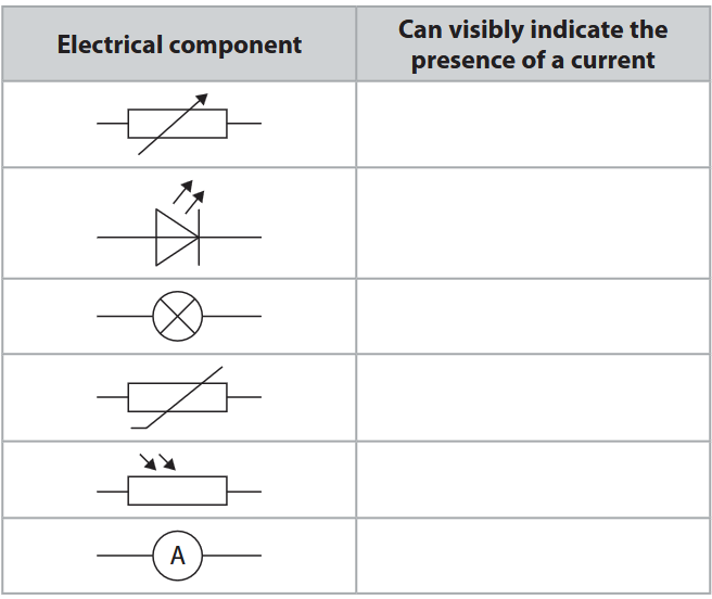
Complete the table by placing ticks \((\checkmark)\) to show whether each component can visibly indicate the presence of a current in a circuit. (3)
(b) Diagram 1 shows an electrical circuit containing a cell and component X.
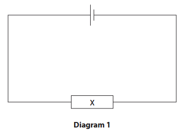
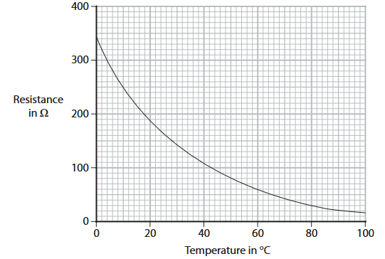
The graph shows how the resistance of component X varies with temperature.
(i) Give the name of component X. (1)
(ii) Using the graph, determine the resistance of component X when its temperature is \(50\,^\circ\mathrm{C}\). (1)
resistance = __________________ \(\Omega\)
(iii) The cell in diagram 1 has a voltage of \(9.0\,\mathrm{V}\).
Calculate the current in component X when its temperature is \(50\,^\circ\mathrm{C}\).
Use the formula
voltage = current \(\times\) resistance (3)
current = __________________ \(\mathrm{A}\)
(iv) The circuit in diagram 1 is modified by adding a second identical component X in series with the other components.
The temperatures of the first component X and second component X are reduced to \(26\,^\circ\mathrm{C}\).
Explain how the resistance of the circuit is affected by these changes. (4)
Syllabus Topic Codes (Edexcel International GCSE Physics 4PH1):
• 2.13: Resistance and factors affecting resistance — parts (b)(i), (b)(ii) and (b)(iv)
• 2.14: Thermistors and temperature-dependent resistance — parts (b)(i), (b)(ii) and (b)(iv)
• 2.16: Current, voltage and resistance using \(V=IR\) — part (b)(iii)
• 2.18: Series circuits and total resistance — part (b)(iv)
▶️ Answer/Explanation
(a) Components that visibly indicate current [3 marks]
The components that visibly indicate the presence of a current are:
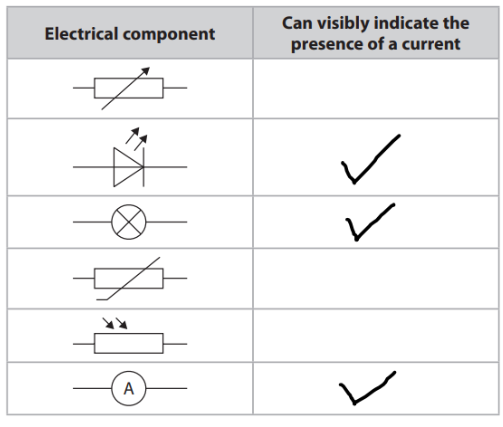
The LED and lamp produce visible light when current flows, while the ammeter visibly indicates current by giving a meter reading.
(b)(i) Name of component X [1 mark]
Correct Answer: \( \boxed{\mathrm{NTC\ thermistor}} \)
The graph shows that the resistance decreases as temperature increases. This is characteristic of a negative temperature coefficient (NTC) thermistor.
(b)(ii) Resistance at \(50\,^\circ\mathrm{C}\) [1 mark]
Reading from the graph at \(50\,^\circ\mathrm{C}\):
\(R\approx80\,\Omega\)
Final Answer: \( \boxed{80\,\Omega} \)
(b)(iii) Current through component X [3 marks]
1. Use Ohm’s law:
\(V=IR\)
2. Rearrange for current:
\(I=\dfrac{V}{R}\)
3. Substitute the values:
\(I=\dfrac{9.0}{80}\)
\(I=0.1125\,\mathrm{A}\)
To an appropriate number of significant figures:
\(I\approx0.11\,\mathrm{A}\)
Final Answer: \( \boxed{0.11\,\mathrm{A}} \)
(b)(iv) Effect of the changes on circuit resistance [4 marks]
1. Determine the resistance of each thermistor at \(26\,^\circ\mathrm{C}\):
From the graph, the resistance of one component X at \(26\,^\circ\mathrm{C}\) is approximately \(160\,\Omega\).
2. The two components are identical:
Each thermistor has a resistance of approximately \(160\,\Omega\).
3. Components in series have their resistances added:
\(R_{\mathrm{total}}=R_1+R_2\)
\(R_{\mathrm{total}}=160+160\)
\(R_{\mathrm{total}}=320\,\Omega\)
4. Therefore, the resistance of the circuit increases.
The temperature reduction causes the resistance of each NTC thermistor to increase. Adding the second identical thermistor in series then adds another \(160\,\Omega\) to the circuit resistance.
Final Answer: \( \boxed{R_{\mathrm{total}}\approx320\,\Omega} \). The resistance of the circuit increases because the thermistors have a higher resistance at the lower temperature and their resistances add in series.
Question
A student builds this electric circuit to measure the temperature of a room.
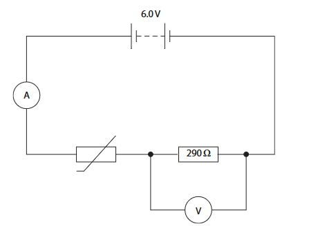
(a) At \(20^\circ\mathrm{C}\), the voltage across the thermistor is \(3.9\,\mathrm{V}\).
(i) Explain why the reading on the voltmeter is \(2.1\,\mathrm{V}\). (2)
(ii) The resistor in the circuit has a resistance of \(290\,\Omega\).
Calculate the current in the resistor.
Use the formula
\(\mathrm{voltage}=\mathrm{current}\times\mathrm{resistance}\)
current = __________________ \(\mathrm{A}\)
(iii) State the reading on the ammeter. (1)
ammeter reading = __________________ \(\mathrm{A}\)
(iv) Calculate the resistance of the thermistor. (3)
resistance = __________________ \(\Omega\)
(b) The student observes that the voltmeter reading increases as the temperature of the room increases.
(i) Explain this observation. (3)
(ii) The student wants to use the circuit as a temperature-measuring device.
They have this additional equipment:
- a large beaker
- water at different temperatures
- a thermometer
Describe what measurements the student needs to take so that the circuit could be used as a temperature-measuring device.
Assume that the thermistor in the circuit is waterproof.
You may draw a diagram to help your answer. (3)
Syllabus Topic Codes (Edexcel International GCSE Physics 4PH1):
• 2.11–2.12: Resistance of LDRs and thermistors; lamps and LEDs — parts (a)(iv) and (b)(i)
• 2.13–2.15: Voltage, current, resistance, charge and time — parts (a)(i)–(a)(iv)
• 2.9: Current–voltage characteristics — relevant to the relationship between electrical readings and circuit behaviour
▶️ Answer/Explanation
(a)(i) Voltmeter reading [2 marks]
- The thermistor and resistor are connected in series.
- The voltages across components in series add to the supply voltage.
Therefore,
\(V_{\mathrm{resistor}}=6.0-3.9\)
\(V_{\mathrm{resistor}}=2.1\,\mathrm{V}\)
Final Answer: \( \boxed{2.1\,\mathrm{V}} \)
(a)(ii) Current in the resistor [3 marks]
1. Use the equation:
\(V=IR\)
2. Rearrange for current:
\(I=\dfrac{V}{R}\)
3. Substitute the values:
\(I=\dfrac{2.1}{290}\)
\(I\approx0.00724\,\mathrm{A}\)
To an appropriate number of significant figures, \(I\approx0.0072\,\mathrm{A}\).
Final Answer: \( \boxed{0.0072\,\mathrm{A}} \)
(a)(iii) Ammeter reading [1 mark]
The resistor and thermistor are connected in series, so the current is the same throughout the series circuit.
Final Answer: \( \boxed{0.0072\,\mathrm{A}} \)
(a)(iv) Resistance of the thermistor [3 marks]
1. Use the equation:
\(V=IR\)
2. Rearrange for resistance:
\(R=\dfrac{V}{I}\)
3. Substitute the thermistor voltage and current:
\(R=\dfrac{3.9}{0.0072}\)
\(R\approx542\,\Omega\)
Final Answer: \( \boxed{542\,\Omega} \)
(b)(i) Effect of increasing temperature [3 marks]
- As the temperature increases, the resistance of the thermistor decreases.
- This causes the current in the series circuit to increase.
- The resistance of the \(290\,\Omega\) resistor remains constant, so \(V=IR\) shows that the voltage across this resistor increases. Since the supply voltage is fixed at \(6.0\,\mathrm{V}\), the voltage across the thermistor therefore decreases.
However, the mark scheme states that the voltmeter reading increases as temperature increases. This is consistent with the thermistor resistance decreasing and the fixed resistor being the component whose voltage increases as the current increases.
Thus, the voltmeter reading increases because the increased current causes a greater voltage across the fixed resistor while the total supply voltage remains \(6.0\,\mathrm{V}\).
(b)(ii) Calibrating the circuit as a temperature-measuring device [3 marks]
The circuit needs to be calibrated by comparing known temperatures with corresponding electrical readings.
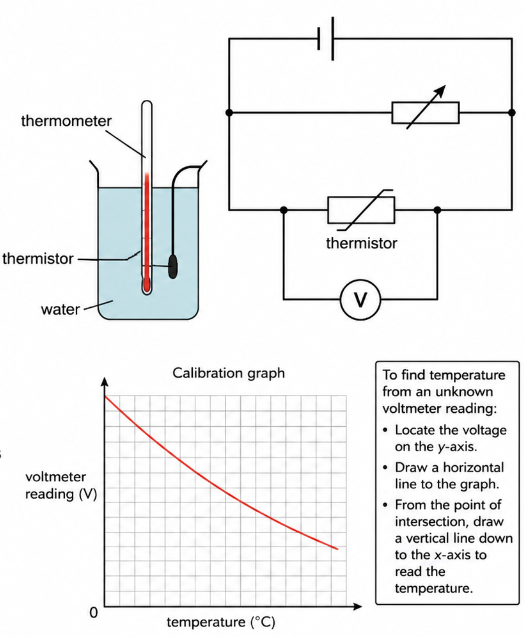
- Place the thermistor and thermometer into a beaker of water.
- Use water at a range of different temperatures and allow the thermistor and thermometer to reach the same temperature.
- For each temperature, record the thermometer temperature and the corresponding voltmeter reading.
- Plot a graph of voltmeter reading against temperature.
- Use the calibration graph to determine the temperature from an unknown voltmeter reading.
Example calibration:
\(\mathrm{temperature}\longleftrightarrow\mathrm{voltmeter\ reading}\)
Final Answer: Measure the voltage for a range of known temperatures, plot a calibration graph of voltage against temperature, and use the graph to determine unknown temperatures.
Question
The diagram shows an electric circuit used to determine the brightness of the light in a room.
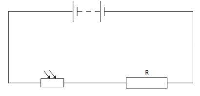
The circuit contains a light-dependent resistor (LDR) connected in series with resistor \(R\) and a battery.
(a) Add a voltmeter to the diagram to measure the voltage of resistor \(R\). (2 marks)
The voltmeter should be connected in parallel with resistor \(R\).
(b)(i) State the formula linking voltage, current and resistance. (1 mark)
________________________________________________________________________________________________
(ii) The voltage across resistor \(R\) is \(1.9\,\mathrm{V}\).
The resistance of resistor \(R\) is \(800\,\Omega\).
Calculate the current in the circuit.
Give your answer in milliamps, \(\mathrm{mA}\). (3 marks)
(c) Explain why the voltage across the light-dependent resistor (LDR) decreases if the brightness of the light in the room increases. (4 marks)
________________________________________________________________________________________________
________________________________________________________________________________________________
________________________________________________________________________________________________
(d) Another resistor is connected in parallel with resistor \(R\). The new resistor has a higher resistance than resistor \(R\).
Explain what happens to the current in the LDR in the circuit diagram.
Assume that the brightness of the light in the room remains constant. (2 marks)
________________________________________________________________________________________________
________________________________________________________________________________________________
Syllabus Topic Codes (Edexcel International GCSE Physics 4PH1):
• 2.13–2.15: Voltage, current and resistance — parts (b)(i), (b)(ii)
• 2.11–2.12: Resistance of LDRs and thermistors; lamps and LEDs — part (c)
• 2.7–2.8: Series and parallel circuits and current in them — part (d)
▶️ Answer/Explanation and Mark Scheme
(a) Voltmeter connection [2 marks]
- Use the correct voltmeter symbol: \( \mathrm{V} \) inside a circle.
- Connect the voltmeter in parallel with resistor \(R\).
(b)(i) Formula [1 mark]
\(\boxed{V=IR}\)
(b)(ii) Current [3 marks]
Rearrange \(V=IR\):
\(I=\dfrac{V}{R}\)
\(I=\dfrac{1.9}{800}=0.002375\,\mathrm{A}\)
Since \(1\,\mathrm{A}=1000\,\mathrm{mA}\),
\(I=2.375\,\mathrm{mA}\)
Answer: \( \boxed{2.38\,\mathrm{mA}} \)
(c) Effect of increased brightness [4 marks]
- As the brightness increases, the resistance of the LDR decreases.
- The total resistance of the circuit therefore decreases.
- The current in the circuit increases.
- The battery voltage remains constant, so a greater proportion of the voltage is across the fixed resistor \(R\), causing the voltage across the LDR to decrease.
(d) Effect of adding a parallel resistor [2 marks]
- Adding a resistor in parallel provides an additional path for current, so the total resistance of the parallel combination decreases.
- The total current, and therefore the current through the LDR, increases.
Total: \(12\) marks
Question
A student investigates the voltage-current characteristics of an unknown component, X.
(a) The student is given this equipment to investigate component X.
• battery
• variable resistor
• ammeter
• voltmeter
• connecting wires
The diagram shows an incomplete circuit containing the battery and component X. Complete the diagram by drawing a circuit the student could use for their investigation.

(b) The graph shows the results of the investigation.

(i) Draw a line of best fit on the graph.
(ii) Calculate the resistance of component X when the voltage is \(4.2\,\mathrm{V}\). Give the unit.
(iii) Which of these is equivalent to \(4.2\,\mathrm{V}\)?
A 4.2 coulombs per second (C/s)
B 4.2 seconds per joule (s/J)
C 4.2 joules per second (J/s)
D 4.2 joules per coulomb (J/C)
(iv) The student concludes that component X is a filament lamp. Comment on the student’s conclusion.
Syllabus Topic Codes (Edexcel International GCSE Physics 4PH1):
• 2.13: Relationship between voltage, current and resistance, \(V=IR\) — part (b)(ii)
• 2.20: Voltage as energy transferred per unit charge and the volt as a joule per coulomb — part (b)(iii)
• 2.10: Qualitative effect of changing resistance on current — part (b)(iv)
▶️ Answer/Explanation
Ans
(a) circuit symbols for variable resistor, ammeter and voltmeter drawn correctly;
variable resistor drawn in series with battery and component X;
ammeter drawn in series with component X;
voltmeter drawn in parallel with component X;
(b) (i) straight line of best fit drawn with points distributed equally either side;
(ii) use of voltage = current × resistance;
correct reading of current from graph;
substitution OR rearrangement;
evaluation;
matching unit;
e.g.
V = I × R
current = 2.35 (×10⁻³) (A)
4.2 = 2.35 (×10⁻³) × R OR R = V / I
(resistance =) 1800
ohms / Ω
(iii) D (4.2 joules per coulomb); 1
A is incorrect because this is the unit for current
B is incorrect because this is the reciprocal of the unit for power
C is incorrect because this is the unit for power
(iv) graph for lamp should be a curve;
(because) a lamp does not obey Ohm’s Law/ lamp
does not have I directly proportional to V.
component X is a resistor;
Questions
The diagram shows a domestic lighting circuit.
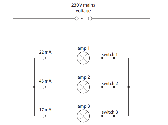
(a) Explain an advantage of using this circuit for domestic lighting.
(b) When switch 1 is closed, the current in lamp 1 is 22mA.
(i) Give the name of the charged particle that moves in an electric current.
(ii) Show that lamp 1 has a power of about 5W.
(iii) Calculate the energy transferred by lamp 1 when it is on for 30 seconds.
(c) The circuit is connected to the mains supply. Mains voltage is 230V.
(i) State what is meant by the term voltage.
(ii) Switches 1 and 3 are closed, which turn on lamps 1 and 3. Switch 2 is open. Calculate the current in the mains supply
Syllabus Topic Codes (Edexcel International GCSE Physics 4PH1):
• 4.1: Electric current and charge carriers — part (b)(i)
• 4.7: Electrical power and the relationship between power, current and voltage — part (b)(ii)
• 4.8: Energy transferred in electrical circuits — part (b)(iii)
• 4.4: Potential difference as energy transferred per unit charge — part (c)(i)
• 4.10: Current in parallel circuits — part (c)(ii)
▶️Answer/Explanation
Ans
(a) idea that lamps can be controlled independently;
(because) circuit is a parallel circuit;
(b) (i) electron(s);
(ii) substitution into formula;
conversion from mA to A;
evaluation to 2 or more s.f.;
e.g.
power = \(230 × 22(×10^{-3})\)
power = 230 × 0.022
power = 5.1 (W)
(iii) substitution into P = E/t;
rearrangement;
evaluation;
e.g.
5 = E / 30
E = 5 × 30
E = 150 (J)
(c) (i) energy (transferred) per unit charge (passed);
(ii) any attempt to add any currents together;
(current =) 39 (mA);
Questions
A student uses the circuit shown in diagram 1 to investigate how the current changes with voltage for a filament lamp.

(a)
(i) Give the name of component Y. (1)
(ii) Give a reason why component Y is included in the circuit. (1)
(b) The graph shows some of the student’s results.

(i) State the formula linking charge, current and time. (1)
(ii) Determine the current in the lamp when the voltage across the lamp is \(10\,\mathrm{V}\). (1)
(iii) Calculate the charge transferred through the lamp in \(30\,\mathrm{s}\) when the voltage across the lamp is \(10\,\mathrm{V}\). Give the unit. (3)
(iv) Calculate the time for the lamp to transfer \(250\,\mathrm{J}\) of energy when the voltage across the lamp is \(10\,\mathrm{V}\). (3)
(v) The student disconnects the cell and reconnects it with its terminals reversed. Complete the graph to show how the current in the lamp varies with voltage across the lamp when the cell is connected with its terminals reversed. (2)
(c) The student replaces the filament lamp with a light emitting diode (LED) and replaces the cell with an alternating current (a.c.) power supply, as shown in diagram 2. The student also removes the ammeter and voltmeter from the circuit.

Explain why the LED flashes on and off in this circuit. (2)
Syllabus Topic Codes (Edexcel International GCSE Physics 4PH1):
• 2.9: Current-Voltage Characteristics — parts (b)(ii) and (b)(v)
• 2.13–2.15: Voltage, Current, Resistance, Charge, and Time — parts (b)(i) and (b)(iii)
• 2.20–2.21: Voltage, Energy Transfer, and Charge — part (b)(iv)
• 2.6: Alternating Current (AC) and Direct Current (DC) — part (c)
• 2.11–2.12: Resistance of LDRs and Thermistors; Lamps and LEDs — part (c)
▶️ Answer/Explanation
(a)(i) Component Y [1 mark]
Component Y is a variable resistor.
(a)(ii) Purpose of component Y [1 mark]
It allows the current in the circuit and therefore the voltage across the lamp to be varied.
(b)(i) Charge, current and time [1 mark]
\(\boxed{Q=It}\)
where \(Q\) is charge in coulombs (\(\mathrm{C}\)), \(I\) is current in amperes (\(\mathrm{A}\)), and \(t\) is time in seconds (\(\mathrm{s}\)).
(b)(ii) Current at \(10\,\mathrm{V}\) [1 mark]
From the graph, when the voltage across the lamp is \(10\,\mathrm{V}\), the current is:
\(\boxed{I=0.48\,\mathrm{A}}\)
(b)(iii) Charge transferred [3 marks]
Using:
\(Q=It\)
\(Q=0.48\times30\)
\(Q=14.4\,\mathrm{C}\)
Therefore, to an appropriate level of precision:
\(\boxed{Q\approx14\,\mathrm{C}}\)
(b)(iv) Time for \(250\,\mathrm{J}\) of energy transfer [3 marks]
Use:
\(E=VIt\)
Substituting \(E=250\,\mathrm{J}\), \(V=10\,\mathrm{V}\), and \(I=0.48\,\mathrm{A}\):
\(250=10\times0.48\times t\)
\(t=\dfrac{250}{4.8}\)
\(t\approx52.1\,\mathrm{s}\)
\(\boxed{t\approx52\,\mathrm{s}}\)
(b)(v) Reversed cell [2 marks]
The current and voltage both reverse direction. Therefore, the original current-voltage curve should be rotated through \(180^\circ\) into the negative voltage and negative current quadrant.
The curve should:
- pass through the origin \((0,0)\);
- have a similar shape to the original curve;
- extend approximately to \((-12\,\mathrm{V},-0.5\,\mathrm{A})\).
(c) LED flashing on and off [2 marks]
The a.c. supply causes the current to continually change direction.
An LED only allows current to flow in one direction, so it emits light during the half-cycle when the current flows in the forward direction. It does not light when the current reverses.
Therefore, the LED flashes on and off.
Questions
Diagram 1 shows a light-emitting diode (LED) and a resistor in series with a cell and an ammeter.

(a) The voltage across the LED is \(0.63\,\mathrm{V}\). Calculate the current in the circuit. Give your answer in milliamps. (3)
(b) Diagram 2 shows a second LED and an extra resistor connected in parallel with the cell.

The resistor and the LED are the same as the components used in diagram 1. The two resistors are identical and the two LEDs are identical. Explain how the ammeter reading will change. (4)
Syllabus Topic Codes (Edexcel International GCSE Physics 4PH1):
• 2.10: Resistance and Current — part (a)
• 2.12: Lamps and LEDs — parts (a) and (b)
▶️ Answer/Explanation
(a) Current in the circuit [3 marks]
The cell provides \(1.5\,\mathrm{V}\). Therefore, the voltage across the resistor is:
\(V_R=1.5-0.63\)
\(V_R=0.87\,\mathrm{V}\)
Using:
\(V=IR\)
Rearranging:
\(I=\dfrac{V}{R}\)
\(I=\dfrac{0.87}{95}\)
\(I=0.00915\ldots\,\mathrm{A}\)
Converting to milliamps:
\(I=0.00915\times1000\)
\(I\approx9.2\,\mathrm{mA}\)
\(\boxed{I=9.2\,\mathrm{mA}}\)
(b) Effect of adding the second parallel branch [4 marks]
- The addition of the second identical branch provides an extra path for current.
- The two identical resistors are connected in parallel, so their combined resistance is half the resistance of one resistor.
- The voltage across each parallel branch is the same as the voltage across the original branch.
- Therefore, the total current supplied by the cell, and hence the ammeter reading, doubles.
For two identical resistances \(R\) in parallel:
\(\dfrac{1}{R_{\mathrm{total}}}=\dfrac{1}{R}+\dfrac{1}{R}=\dfrac{2}{R}\)
Therefore:
\(R_{\mathrm{total}}=\dfrac{R}{2}\)
Since the total resistance is halved while the supply voltage remains unchanged, the total current doubles.
\(\boxed{\text{Ammeter reading doubles}}\)
Questions
The diagram shows four graphs, P, Q, R and S. Each graph shows a different relationship between current and time.

The table gives descriptions of the relationships between current and time shown by graphs P, Q, R and S. Complete the table by giving the correct graph for each description.

Syllabus Topic Codes (Edexcel International GCSE Physics 4PH1):
▶️ Answer/Explanation
Answer [4 marks]
One mark is awarded for each correctly completed row of the table.
The graphs should be matched by examining how the current changes with time in each case.
For example, a horizontal line represents a constant current, while an upward or downward slope represents a current that is increasing or decreasing with time.

Questions
This question is about electrical resistors.
(a) Diagram 1 shows a \(13\,\mathrm{k\Omega}\) resistor connected to a \(5.8\,\mathrm{V}\) battery.

(i) State the formula linking voltage, current and resistance.
(ii) Calculate the current in the resistor.
(b) Diagram 2 shows a \(200\,\Omega\) resistor connected in parallel with a \(13\,\mathrm{k\Omega}\) resistor.

(i) Complete the circuit diagram by adding a suitable meter to diagram 2 to measure the current in the \(13\,\mathrm{k\Omega}\) resistor.
(ii) The switch in the circuit is closed. Explain what happens to the current in the \(13\,\mathrm{k\Omega}\) resistor and the current in the battery.
Syllabus Topic Codes (Edexcel International GCSE Physics 4PH1):
• 2.13–2.15: Voltage, Current, Resistance, Charge, and Time — part (a)
• 2.7–2.8: Series and Parallel Circuits and Current in Them — part (b)
• 2.18–2.19: Voltage in Parallel Circuits and Series Circuit Calculations — part (b)(ii)
▶️ Answer/Explanation
(a)(i) Voltage, current and resistance
The relationship is:
\(\boxed{V=IR}\)
(a)(ii) Current in the resistor
The resistance is:
\(R=13\,\mathrm{k\Omega}=13\times10^3\,\Omega\)
Using \(V=IR\):
\(5.8=I(13\times10^3)\)
\(I=\dfrac{5.8}{13\times10^3}\)
\(I=4.46\times10^{-4}\,\mathrm{A}\)
\(\boxed{I=4.5\times10^{-4}\,\mathrm{A}}\)
(b)(i) Measuring the current
An ammeter should be connected in series with the \(13\,\mathrm{k\Omega}\) resistor so that the current through that resistor passes through the meter.
(b)(ii) Effect of closing the switch
Current in the \(13\,\mathrm{k\Omega}\) resistor:
- The voltage across the \(13\,\mathrm{k\Omega}\) resistor remains the same because it is connected in parallel with the battery.
- Its resistance is unchanged.
- Therefore, from \(I=\dfrac{V}{R}\), the current through the \(13\,\mathrm{k\Omega}\) resistor stays the same.
Current in the battery:
- Adding the \(200\,\Omega\) resistor in parallel provides an additional path for current.
- The total resistance of the circuit decreases.
- The battery voltage remains the same.
- Therefore, the total current supplied by the battery increases.
Thus, the branch current through the \(13\,\mathrm{k\Omega}\) resistor is unchanged, while the total current from the battery increases.
Question
A student investigates how the current in a filament lamp varies with the voltage across it. The student has this equipment
• filament lamp
• cell
• variable resistor
• ammeter
• voltmeter
• connecting wires
(a) Draw a circuit diagram that the student could use for this investigation.
(b) The table gives the student’s results.

(i) Plot the results on the grid.
(ii) Draw the curve of best fit.

(c) The filament of the lamp is made of metal. The student suggests that a straight line on the graph is more appropriate than a curve because current is directly proportional to voltage for a metal.
(i) Suggest how the student could improve their investigation to find out whether a straight line or curve is more appropriate.
(ii) Explain why the student should not expect current to be proportional to voltage for this filament lamp.
Syllabus Topic Codes (Edexcel International GCSE Physics 4PH1):
• 2.9: Current–Voltage Characteristics — parts (b) and (c)
• 2.10: Resistance and Current — part (c)(ii)
• 2.11–2.12: Resistance of LDRs and Thermistors; Lamps and LEDs — filament lamp behaviour
▶️ Answer/Explanation
(a) Circuit diagram [4 marks]
The circuit should contain all the components connected correctly:
- The cell, variable resistor, ammeter and filament lamp are connected in series.
- The ammeter is connected in series with the filament lamp to measure the current through it.
- The voltmeter is connected in parallel across the filament lamp to measure the voltage across it.
The variable resistor is used to change the current and voltage so that several readings can be taken.
(b)(i) Plotting the results [1 mark]
Plot each pair of voltage and current readings accurately on the grid. The points should be positioned according to the values in the table.
(b)(ii) Curve of best fit [1 mark]
Draw a smooth curve of best fit through the plotted points. The curve should pass within approximately half a small square of all the points.
(c)(i) Improving the investigation [1 mark]
The student could take more measurements at different voltages, particularly over a wider range of voltage values. This would provide more data points and make it easier to determine whether the relationship is a straight line or a curve.
(c)(ii) Why current is not proportional to voltage [2 marks]
- As current flows through the filament, the filament heats up.
- The resistance of the metal filament changes as its temperature increases.
- Therefore, the resistance is not constant, so current is not directly proportional to voltage.
For a constant resistance, Ohm’s law gives:
\(V=IR\)
However, the filament becomes hotter as the current increases, causing its resistance to increase. This makes the \(I\)-\(V\) relationship non-linear and produces a curve rather than a straight line.