
Edexcel iGCSE Physics (4PH1) 6.2 Magnetism Exam Style Question Paper 1B - New Syllabus
Question
This question is about magnetic fields.
(a) Diagram 1 shows the poles of two strong bar magnets being held close together.
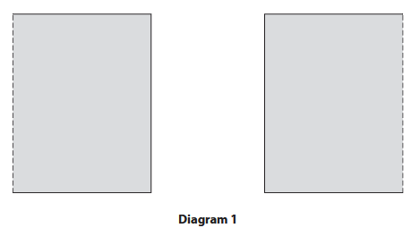
There is a uniform magnetic field between the poles of the bar magnets.
Complete diagram 1 by drawing magnetic field lines to show the uniform magnetic field.
You should label the poles of the bar magnets. (4)
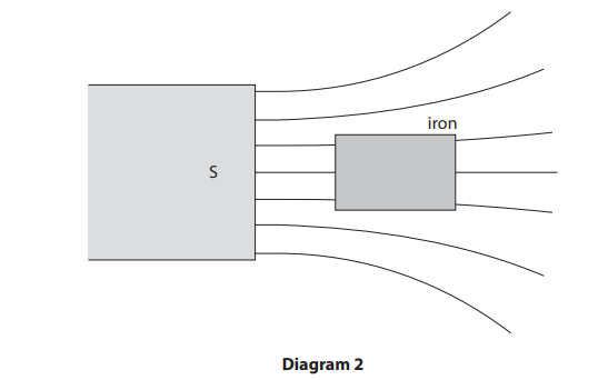
(b) Diagram 2 shows a strong magnet attracting an iron block.
(i) The iron block becomes magnetised when it is in the magnetic field of the strong magnet.
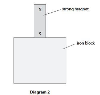
Label the magnetic poles on the magnetised iron block in diagram 2. (1)
Top of iron block: __________________
Bottom of iron block: __________________
(ii) A student takes the strong magnet away from the iron block.
The student suggests they can permanently use the iron block to attract small pieces of iron.
Explain whether the student’s suggestion is correct. (2)
Syllabus Topic Codes (Edexcel International GCSE Physics 4PH1):
• 6.11: Magnetisation of magnetic materials — part (b)(i)
• 6.11: Permanent and temporary magnetism — part (b)(ii)
▶️ Answer/Explanation
(a) Uniform magnetic field [4 marks]
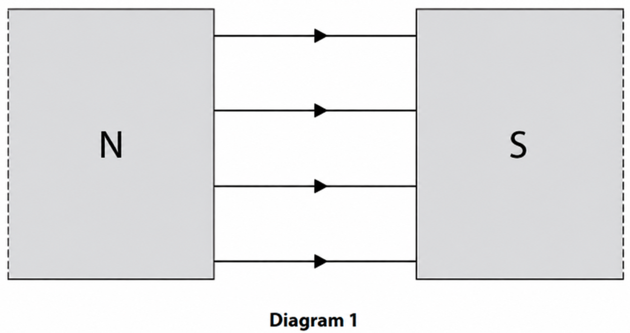
- The facing poles must be opposite poles, so one pole is \(N\) and the other is \(S\).
- Draw horizontal, straight magnetic field lines joining the two poles.
- Draw at least three field lines equally spaced between the poles to represent a uniform field.
- Draw arrows on the field lines pointing from the north pole to the south pole.
A uniform magnetic field is represented by straight, parallel and equally spaced field lines. The arrows show the direction from \(N\) to \(S\).
(b)(i) Poles induced in the iron block [1 mark]
The lower end of the strong magnet is \(S\). The end of the iron block nearest this \(S\) pole becomes \(N\), because unlike magnetic poles attract.
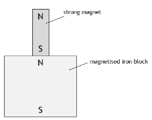
Correct labels:
- Top of the iron block: \(N\)
- Bottom of the iron block: \(S\)
(b)(ii) Permanent magnetism [2 marks]
Correct Answer: The student’s suggestion is not correct.
- The iron block is a magnetically soft material.
- It loses its magnetism when the strong magnet is removed, so it cannot permanently attract pieces of iron.
The strong magnet temporarily magnetises the iron block by inducing magnetic poles in it. Once the external magnetic field is removed, the induced magnetism is largely lost.
Final Answer: No. The iron is a soft magnetic material, so it loses its induced magnetism when the strong magnet is removed and cannot be used permanently as a magnet.
Question
This question is about magnetism.
(a) Diagram 1 shows the ends of two strong bar magnets and the space between the bar magnets.
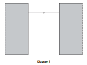
There is a uniform magnetic field in the space between the bar magnets.
(i) One of the magnetic field lines has already been drawn.
Complete the diagram by drawing three more magnetic field lines and labelling the poles of the bar magnets. (3 marks)
The three additional field lines should be straight, parallel and equally spaced, with arrows pointing from the north pole to the south pole.
(ii) Describe a method a student could use to show the shape and direction of the magnetic field between the bar magnets.
You may draw a diagram to help your answer. (3 marks)
____________________________________________________________
____________________________________________________________
(iii) Name a magnetically soft material. (1 mark)
____________________________________________________________
(b) A student investigates how the length, \(L\), of a current-carrying wire in a magnetic field affects the size of the force on the wire.
The student uses a power supply and keeps the current in the wire constant. They use the same magnet throughout the experiment.
Diagram 2 shows part of the student’s equipment.
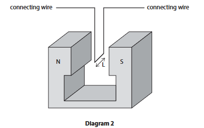
(i) Add one tick (\(\checkmark\)) to each row to show whether each variable is an independent, dependent or control variable. (3 marks)
| Variable | Independent | Dependent | Control |
|---|---|---|---|
| current | |||
| length of wire in field | |||
| force on wire | |||
| magnetic field strength |
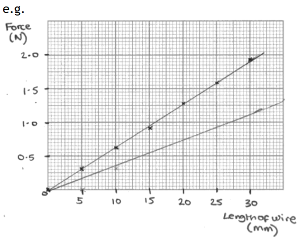
(ii) Table 2 shows the student’s results. Plot a graph of the results on the grid. (3 marks)
| Length of wire in field / mm | Force / N |
|---|---|
| 0 | 0.00 |
| 5 | 0.32 |
| 10 | 0.64 |
| 15 | 0.92 |
| 20 | 1.28 |
| 25 | 1.58 |
| 30 | 1.92 |
(iii) Draw a line of best fit. (1 mark)
____________________________________________________________
(iv) The student repeats the experiment but with a smaller current in the wire.
Draw another line on the graph to show the expected results when using a smaller current. (2 marks)
Syllabus Topic Codes (Edexcel International GCSE Physics 4PH1):
• 6.6: Core Practical: Magnetic field patterns — part (a)(ii)
• 6.2–6.3: Magnetic materials and hard and soft magnetic materials — part (a)(iii)
• 6.12–6.14: Force on a current-carrying conductor — parts (b)(i), (b)(ii), (b)(iii), (b)(iv)
▶️ Answer/Explanation and Mark Scheme
(a)(i) Magnetic field [3 marks]
- Label the left magnet \(N\) and the right magnet \(S\).
- Draw three additional straight, parallel and equally spaced field lines between the poles.
- Put arrows on all field lines pointing from \(N\) to \(S\).
(a)(ii) Showing the magnetic field [3 marks]
- Place a plotting compass in the region between the magnets.
- Move the compass to different positions and mark the direction of the compass needle at each position.
- Join the points to show the field lines and use the compass direction to determine their direction.
Alternative method: Sprinkle iron filings over paper placed above the magnets and gently tap the paper to reveal the field pattern. Use a plotting compass to determine the field direction.
(a)(iii) \( \boxed{\text{iron}} \) [1 mark]
(b)(i) Variables [3 marks]
| Variable | Independent | Dependent | Control |
|---|---|---|---|
| current | ✓ | ||
| length of wire in field | ✓ | ||
| force on wire | ✓ | ||
| magnetic field strength | ✓ |
(b)(ii) Graph [3 marks]
- Horizontal axis: length of wire in field / mm.
- Vertical axis: force / N.
- Use a suitable scale and plot all seven points accurately. The points should lie close to a straight-line trend.
(b)(iii) Line of best fit [1 mark]
- Draw an appropriate straight line of best fit through the plotted data.
(b)(iv) Smaller current [2 marks]
- Draw a straight line starting at \((0,0)\).
- The new line must have a smaller gradient than the original line.
Physics relationship: \(F=BIL\). Since \(B\) and \(I\) are constant, the force is proportional to the length of wire in the magnetic field.
Total: \(16\) marks
Questions
Diagram 1 shows the magnetic field lines near the south pole of a bar magnet.
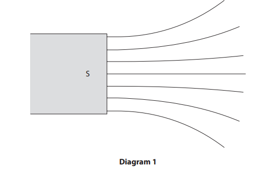
(a) Draw two arrows on the field lines in diagram 1 to show the direction of the magnetic field lines.
(b) Which of these is attracted to the bar magnet if placed in the magnetic field?
A copper
B nickel
C plastic
D zinc
(c) The strength of the magnetic field changes as the distance from the south pole increases. Explain how the magnetic field lines show this.
(d) Diagram 2 shows a small piece of iron that has been placed in the magnetic field.
The piece of iron becomes magnetised when placed in the magnetic field.
(i) Explain why the piece of iron experiences a force towards the south pole of the bar magnet. You may add to diagram 2 to help your answer.
(ii) A student suggests that the piece of iron is now a permanent magnet. Explain why the student is incorrect.
Syllabus Topic Codes (Edexcel International GCSE Physics 4PH1):
• 6.2: Attraction of magnetic substances by magnets — part (b)
• 6.5: Induced magnetism in materials placed in a magnetic field — part (d)(i)
• 6.3: Properties of magnetically soft and hard materials — part (d)(ii)
▶️Answer/Explanation
Ans
(a) arrows drawn on at least two field lines pointing towards the south pole;
(b) B (nickel);
A is incorrect because copper is not a magnetic material
C is incorrect because plastic is not a magnetic material
D is incorrect because zinc is not a magnetic material
(c) field line spacing/density changes (with distance from south pole);
further apart field lines shows weaker field strength;
(d) (i) idea that a north pole is induced on the side of the iron nearest the bar magnet;
idea that opposite poles attract;
(ii) iron is a soft magnetic material;
iron loses its magnetism (when it is removed from the magnetic field);
Question
Diagram 1 shows the magnetic field between the poles of two strong bar magnets.

(a) Add labels to diagram 1 to show the poles of the bar magnets. (1)
(b) The bar magnets are made from steel. Give one reason why steel is a good material for making bar magnets. (1)
(c) Explain how diagram 1 shows a uniform magnetic field. (2)
(d) Diagram 2 shows a metal wire being moved downwards through the uniform field between the poles of the same bar magnets. The orientation of the magnets has not been changed.

(i) Give a reason why a voltage is induced between the ends of the metal wire as it moves between the poles of the bar magnets. (1)
(ii) State two changes that could be made to this arrangement that would increase the magnitude of the induced voltage. (2)
Syllabus Topic Codes (Edexcel International GCSE Physics 4PH1):
• 6.2–6.3: Magnetic Materials, and Hard and Soft Magnetic Materials — part (b)
• 6.7: Uniform Magnetic Fields — part (c)
• 6.15: Induced Voltage — part (d)(i)
• 6.15–6.16: Induced Voltage and Electricity Generation by Induction — part (d)(ii)
▶️ Answer/Explanation
(a) Poles of the bar magnets [1 mark]
The pole on the left should be labelled N and the pole on the right should be labelled S.
(b) Steel as a material for bar magnets [1 mark]
- Steel is a hard magnetic material.
This means that it is difficult to demagnetise, so a steel bar can retain its magnetism.
(c) Uniform magnetic field [2 marks]
The diagram shows a uniform magnetic field because:
- The magnetic field lines are straight and parallel.
- The magnetic field lines are evenly spaced.
Parallel, equally spaced field lines indicate that the magnetic field has the same strength and direction throughout the region.
(d)(i) Induced voltage [1 mark]
- The wire cuts through magnetic field lines as it moves through the magnetic field.
This causes an induced voltage to be produced between the ends of the wire.
(d)(ii) Increasing the induced voltage [2 marks]
Any two of the following:
- Move the wire faster.
- Move the magnets closer together to increase the magnetic field strength in the region between the poles.
- Use stronger magnets.
- Turn the wire into a coil with more turns.
In general, a larger rate of change of magnetic flux through the conductor produces a larger induced voltage.
Question
The diagrams show some equipment that the physicist Ørsted used in an investigation in 1820. Diagram 1 shows the position of eight compass needles around a wire with no current in the wire. The compass needles line up with and show the direction of the Earth’s magnetic field lines.

Diagram 2 shows the position of the same compass needles when a current is in the wire.

(a)(i) Explain why the compass needles turn when the current is switched on.
(ii) Using evidence from the compass needles in diagram 2, draw on diagram 2 the shape and direction of a magnetic field line produced by the current in the wire.
(iii) Suggest what happens to the magnetic field when the current in the wire is reversed.
(b) The current in the wire is turned off. Diagram 3 shows the wire placed in a uniform magnetic field.

The current is now switched on. Draw an arrow to show the direction of the force on the wire.
(c) The power supply in diagram 3 is replaced by an ammeter.
(i) When the wire is moved, a current is detected. Explain which direction the wire is moved in the magnetic field to produce a current in the wire.
(ii) Explain why a current is produced in the wire when the wire is moved in the magnetic field.
Syllabus Topic Codes (Edexcel International GCSE Physics 4PH1):
• 6.8–6.10P: Magnetic Fields around Current-Carrying Conductors and Field Patterns — parts (a)(i)–(iii)
• 6.12–6.14: Force on a Current-Carrying Conductor and the Left-Hand Rule — part (b)
• 6.15: Induced Voltage — part (c)
• 6.16: Electricity Generation by Induction — part (c)
▶️ Answer/Explanation
(a)(i) Effect of current on compass needles [2 marks]
When the current is switched on, the current-carrying wire produces a magnetic field around the wire.
The compass needles experience a magnetic effect and turn to align with the resulting magnetic field.
(a)(ii) Magnetic field around the wire [2 marks]
The magnetic field produced by a straight current-carrying wire consists of concentric circular field lines centred on the wire.
From the directions shown by the compass needles in diagram 2, the field line should have an arrow in the clockwise direction.
(a)(iii) Reversing the current [1 mark]
Reversing the current reverses the direction of the magnetic field around the wire.
(b) Force on the current-carrying wire [2 marks]
The current-carrying wire experiences a force because it is placed in a magnetic field.
Using the direction of the magnetic field and the current shown in diagram 3, the force on the wire is directed upwards.
Therefore, draw the arrow vertically upwards.
(c)(i) Direction of movement [2 marks]
The wire must be moved upwards or downwards, so that it moves across the magnetic field lines.
Moving the wire across the field lines causes the magnetic field lines to be cut by the wire.
(c)(ii) Why a current is produced [2 marks]
When the wire moves through the magnetic field, it cuts magnetic field lines. This induces a voltage across the wire.
Because the circuit is complete, the induced voltage causes a current to flow.
This is the principle of electromagnetic induction.
Question
This question is about magnets.
(a) Which of these substances is not attracted to a bar magnet?
A cobalt
B copper
C iron
D nickel
(b) Diagram 1 shows a bar magnet.

Draw magnetic field lines on diagram 1 to show the shape and direction of the magnetic field around the bar magnet.
(c) Some bar magnets are made of steel. Explain why steel is a good material for making bar magnets.
(d) Diagram 2 shows a cross-section through a wire placed between two magnetic poles. The direction of the current in the wire is out of the page.

(i) Draw an arrow on diagram 2 to show the direction of the force on the wire due to the magnetic field. Assume that the magnetic field is uniform.
(ii) State two changes that could be made that would decrease the magnitude of the force on the wire in diagram 2.
Syllabus Topic Codes (Edexcel International GCSE Physics 4PH1):
• 6.4: Magnetic Field Lines — part (b)
• 6.7: Uniform Magnetic Fields — part (d)
• 6.12–6.14: Force on a Current-Carrying Conductor and the Left-Hand Rule — parts (d)(i)–(ii)
▶️ Answer/Explanation
(a) Magnetic materials [1 mark]
The correct answer is B, copper.
Cobalt, iron, and nickel are magnetic materials and are attracted to a bar magnet. Copper is not attracted to a bar magnet.
(b) Magnetic field lines [3 marks]
Draw at least two complete magnetic field lines around the bar magnet. The field lines should:
- Connect the north pole to the south pole outside the magnet.
- Be curved and should not cross or touch one another.
- Have arrows showing the direction from N to S outside the magnet.

(c) Steel as a material for bar magnets [2 marks]
Steel is a magnetic material and is difficult to demagnetise. Therefore, a steel bar can remain magnetised for a long period of time.
(d)(i) Direction of force [2 marks]
The current is directed out of the page, and the magnetic field is uniform between the poles.
Using the left-hand rule, the force on the wire is directed horizontally to the left.
Therefore, draw a horizontal arrow pointing to the left.

(d)(ii) Reducing the force [2 marks]
Any two suitable changes include:
- Use a weaker magnetic field.
- Move the magnets further apart.
- Use weaker magnets.
- Reduce the current in the wire.
- Decrease the diameter of the wire.
- Decrease the voltage of the power supply.
The force on a current-carrying conductor depends on the magnetic field strength and the current, so reducing either of these reduces the force.