
Edexcel iGCSE Physics (4PH1) 6.3 Electromagnetism Exam Style Question Paper 1B - New Syllabus
Question
The diagram shows a simple direct current (d.c.) electric motor.
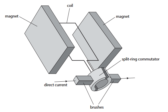
Explain why the coil turns continuously when the motor is connected to a direct current supply.
You should refer to the brushes and the split-ring commutator in your answer. (6)
Syllabus Topic Codes (Edexcel International GCSE Physics 4PH1):
• 6.8–6.10P: Magnetic fields around current-carrying conductors and field patterns — magnetic field produced by the current-carrying coil
▶️ Answer/Explanation
Why the coil turns continuously [6 marks]
- When current flows through the coil, the coil produces a magnetic field.
- The magnetic field of the coil interacts with the magnetic field of the permanent magnets.
- This interaction produces a force on the coil, causing it to rotate.
- The brushes maintain electrical contact with the rotating split-ring commutator and allow current to flow into the coil.
- The split-ring commutator reverses the direction of the current in the coil after each half-turn.
- This reverses the direction of the force on each side of the coil, so the turning effect continues in the same rotational direction.
The current and force are therefore reversed every half-turn, allowing the coil to continue rotating rather than stopping after half a revolution.
Mark scheme points:
- Current-carrying coil has a magnetic field.
- Interaction between magnetic fields produces a force on the coil.
- Brushes maintain sliding electrical contact with the split-ring commutator, allowing current to continue flowing.
- The split-ring commutator reverses the direction of current in the coil.
- This reverses the direction of the force on each side of the coil.
- The current and force are reversed every half-turn, allowing continuous rotation.
Final Answer: The current-carrying coil experiences a force due to its interaction with the magnetic field. The brushes maintain contact with the split-ring commutator, while the commutator reverses the current every half-turn. This reverses the forces on the sides of the coil while maintaining the same turning direction, so the coil continues to rotate.
Question
A student investigates the magnetic force on a current-carrying metal rod.
The student places a U-shaped magnet on a sensitive balance.
They connect a rigid metal rod to a low-voltage power supply, and then fix the rod in place so that it passes between the poles of the magnet.
The diagram shows part of the student’s apparatus.
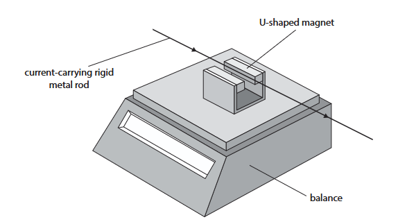
When there is a current in the metal rod, the rod experiences a force due to the magnetic field of the magnet.
The reading on the balance changes because the magnet experiences a force that is the same magnitude as the force on the rod, but in the opposite direction.
(a) The student can increase the current in the metal rod up to a maximum of \(5.0\,\mathrm{A}\).
Suggest why the student should only have the power supply switched on for short periods of time. (2)
(b) Before the power supply is switched on, the reading of the balance is \(194.95\,\mathrm{g}\).
After the power supply is switched on, the reading of the balance is \(193.80\,\mathrm{g}\).
Calculate the force exerted on the current-carrying rod by the magnet. (4)
force = __________________ \(\mathrm{N}\)
(c) The student investigates how the balance reading varies as they change the current in the metal rod.
The table shows the student’s results.
| Current in \(\mathrm{A}\) | Balance reading in \(\mathrm{g}\) |
|---|---|
| \(0.00\) | \(194.95\) |
| \(0.50\) | \(194.80\) |
| \(1.00\) | \(194.65\) |
| \(1.50\) | \(194.50\) |
| \(2.00\) | \(194.35\) |
| \(2.50\) | \(194.20\) |
| \(3.00\) | \(194.05\) |
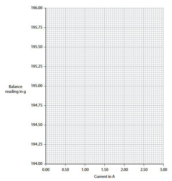
(i) Plot the student’s results on the grid. (1)
(ii) Draw the line of best fit. (1)
(iii) The student changes the connections between the metal rod and the power supply to reverse the direction of the current.
Draw another line on the graph to show how the balance reading will vary with current after this change has been made. (3)
Syllabus Topic Codes (Edexcel International GCSE Physics 4PH1):
• 6.8–6.10P: Magnetic fields produced by magnets and current-carrying conductors — relevant to the interaction between the rod and magnet
• 4.10: Weight and gravitational force — part (b), converting the balance reading change into a force
• 1.8–1.10: Experimental data, graphs and interpretation — part (c)
▶️ Answer/Explanation
(a) Reason for switching on for short periods [2 marks]
- Current in the metal rod produces a heating effect.
- If the current flows for too long, the rod or power supply could become hot, increasing the risk of burns or overheating.
Final Answer: A large current causes heating in the rod and wires. Keeping the supply on for short periods reduces overheating and the risk of burns or fire.
(b) Force on the current-carrying rod [4 marks]
1. Calculate the change in balance reading:
\(\Delta m=194.95-193.80=1.15\,\mathrm{g}\)
2. Convert grams to kilograms:
\(\Delta m=1.15\times10^{-3}\,\mathrm{kg}=0.00115\,\mathrm{kg}\)
3. Use the weight equation:
\(W=mg\)
4. Calculate the force:
\(F=0.00115\times10\)
\(F=0.0115\,\mathrm{N}\)
The force on the magnet and the force on the rod have the same magnitude and opposite directions.
Final Answer: \( \boxed{0.0115\,\mathrm{N}} \)
(c)(i) Plotting the results [1 mark]
The seven points should be plotted correctly:
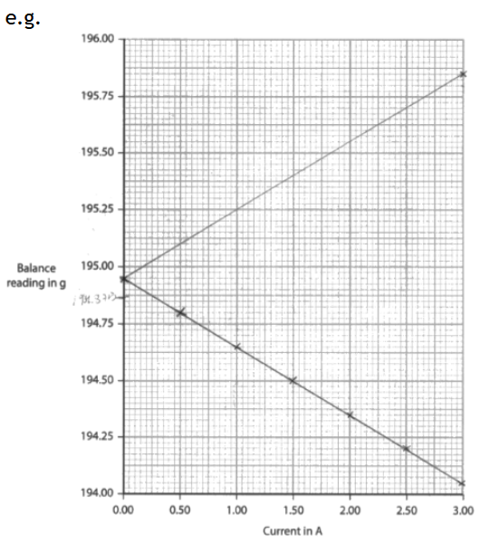
\((0.00,194.95)\), \((0.50,194.80)\), \((1.00,194.65)\), \((1.50,194.50)\), \((2.00,194.35)\), \((2.50,194.20)\), \((3.00,194.05)\).
(c)(ii) Line of best fit [1 mark]
The points form a straight-line relationship. The line of best fit should therefore be a continuous straight line through the centre of the plotted points.
(c)(iii) Reversing the current [3 marks]
- Reversing the current reverses the direction of the magnetic force.
- The force on the magnet therefore acts in the opposite direction, so the balance reading changes in the opposite direction.
- The new graph is a straight line with a positive gradient, starting from the same balance reading at \(I=0\,\mathrm{A}\).
The original results show that increasing current decreases the balance reading. Reversing the current reverses the force, so increasing the magnitude of the current now increases the balance reading.
Final Answer: Draw a straight line with a positive gradient through the point \((0,194.95)\), approximately symmetric with the original line about the \(194.95\,\mathrm{g}\) value at zero current.
Question
This question is about magnetism.
(a) Diagram 1 shows the ends of two strong bar magnets and the space between the bar magnets.
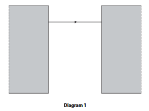
There is a uniform magnetic field in the space between the bar magnets.
(i) One of the magnetic field lines has already been drawn.
Complete the diagram by drawing three more magnetic field lines and labelling the poles of the bar magnets. (3 marks)
The three additional field lines should be straight, parallel and equally spaced, with arrows pointing from the north pole to the south pole.
(ii) Describe a method a student could use to show the shape and direction of the magnetic field between the bar magnets.
You may draw a diagram to help your answer. (3 marks)
____________________________________________________________
____________________________________________________________
(iii) Name a magnetically soft material. (1 mark)
____________________________________________________________
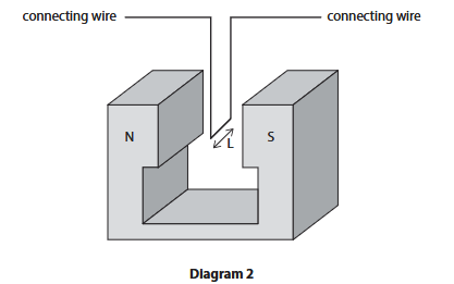
(b) A student investigates how the length, \(L\), of a current-carrying wire in a magnetic field affects the size of the force on the wire.
The student uses a power supply and keeps the current in the wire constant. They use the same magnet throughout the experiment.
Diagram 2 shows part of the student’s equipment.
(i) Add one tick (\(\checkmark\)) to each row to show whether each variable is an independent, dependent or control variable. (3 marks)
| Variable | Independent | Dependent | Control |
|---|---|---|---|
| current | |||
| length of wire in field | |||
| force on wire | |||
| magnetic field strength |
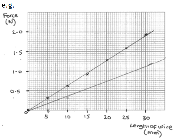
(ii) Table 2 shows the student’s results. Plot a graph of the results on the grid. (3 marks)
| Length of wire in field / mm | Force / N |
|---|---|
| 0 | 0.00 |
| 5 | 0.32 |
| 10 | 0.64 |
| 15 | 0.92 |
| 20 | 1.28 |
| 25 | 1.58 |
| 30 | 1.92 |
(iii) Draw a line of best fit. (1 mark)
____________________________________________________________
(iv) The student repeats the experiment but with a smaller current in the wire.
Draw another line on the graph to show the expected results when using a smaller current. (2 marks)
Syllabus Topic Codes (Edexcel International GCSE Physics 4PH1):
• 6.6: Core Practical: Magnetic field patterns — part (a)(ii)
• 6.2–6.3: Magnetic materials and hard and soft magnetic materials — part (a)(iii)
• 6.12–6.14: Force on a current-carrying conductor — parts (b)(i), (b)(ii), (b)(iii), (b)(iv)
▶️ Answer/Explanation and Mark Scheme
(a)(i) Magnetic field [3 marks]
- Label the left magnet \(N\) and the right magnet \(S\).
- Draw three additional straight, parallel and equally spaced field lines between the poles.
- Put arrows on all field lines pointing from \(N\) to \(S\).
(a)(ii) Showing the magnetic field [3 marks]
- Place a plotting compass in the region between the magnets.
- Move the compass to different positions and mark the direction of the compass needle at each position.
- Join the points to show the field lines and use the compass direction to determine their direction.
Alternative method: Sprinkle iron filings over paper placed above the magnets and gently tap the paper to reveal the field pattern. Use a plotting compass to determine the field direction.
(a)(iii) \( \boxed{\text{iron}} \) [1 mark]
(b)(i) Variables [3 marks]
| Variable | Independent | Dependent | Control |
|---|---|---|---|
| current | ✓ | ||
| length of wire in field | ✓ | ||
| force on wire | ✓ | ||
| magnetic field strength | ✓ |
(b)(ii) Graph [3 marks]
- Horizontal axis: length of wire in field / mm.
- Vertical axis: force / N.
- Use a suitable scale and plot all seven points accurately. The points should lie close to a straight-line trend.
(b)(iii) Line of best fit [1 mark]
- Draw an appropriate straight line of best fit through the plotted data.
(b)(iv) Smaller current [2 marks]
- Draw a straight line starting at \((0,0)\).
- The new line must have a smaller gradient than the original line.
Physics relationship: \(F=BIL\). Since \(B\) and \(I\) are constant, the force is proportional to the length of wire in the magnetic field.
Total: \(16\) marks
Questions
A device called a metal detector can be used to find metal buried underground.

The metal detector has two circuits, each containing a coil of copper wire. Diagram 1 shows the circuit for the transmitter coil.

(a) Suggest why there is a magnetic field around the transmitter coil.
(b) The cell supplies direct current (d.c.). The electronics in diagram 1 change the direct current into alternating current (a.c.) in the coil.
(i) Describe the difference between direct current (d.c.) and alternating current (a.c.).
(ii) Alternating current is supplied to the transmitter coil. Diagram 2 shows a gold ring in the soil below the metal detector.

Explain why there is an alternating current in the gold ring.
(c) Diagram 3 shows the circuit for the receiver coil.

As a result of the alternating current in the gold ring, there is an alternating current in the receiving coil. Explain how an alternating current in the receiving coil causes a sound to be emitted from the loudspeaker.
Syllabus Topic Codes (Edexcel International GCSE Physics 4PH1):
• 6.c: Electromagnetism, Direct Current and Alternating Current — part (b)(i)
• 6.d: Electromagnetic Induction — part (b)(ii)
• 6.c: Motor Effect and Loudspeakers — part (c)
▶️ Answer/Explanation
(a) Magnetic field around the transmitter coil
There is a current flowing through the coil. A current-carrying conductor produces a magnetic field around it.
Answer: The current in the coil produces a magnetic field around the coil.
(b)(i) Direct current and alternating current
- Direct current (d.c.) flows in one direction only.
- Alternating current (a.c.) continuously changes direction.
(b)(ii) Induced current in the gold ring
- The alternating current in the transmitter coil produces a changing magnetic field.
- The changing magnetic field passes through the gold ring, so the ring effectively cuts changing magnetic field lines.
- This changing magnetic field induces a voltage in the gold ring.
- Because the induced voltage continually changes direction, an alternating current flows in the gold ring.
This is an example of electromagnetic induction: a changing magnetic field induces a voltage in a conductor.
(c) Operation of the loudspeaker
- The alternating current flows through the coil in the loudspeaker.
- The current produces a magnetic field around the coil, which interacts with the permanent magnetic field of the loudspeaker.
- This interaction produces a force on the loudspeaker cone.
- Because the current is alternating, the direction of the force continually changes.
- The cone therefore vibrates.
- The vibrating cone produces pressure variations in the air, creating a sound wave.
Therefore: alternating current causes the loudspeaker cone to vibrate, producing sound.
Question
This question is about magnets.
(a) Which of these substances is not attracted to a bar magnet?
A cobalt
B copper
C iron
D nickel
(b) Diagram 1 shows a bar magnet.

Draw magnetic field lines on diagram 1 to show the shape and direction of the magnetic field around the bar magnet.
(c) Some bar magnets are made of steel. Explain why steel is a good material for making bar magnets.
(d) Diagram 2 shows a cross-section through a wire placed between two magnetic poles. The direction of the current in the wire is out of the page.

(i) Draw an arrow on diagram 2 to show the direction of the force on the wire due to the magnetic field. Assume that the magnetic field is uniform.
(ii) State two changes that could be made that would decrease the magnitude of the force on the wire in diagram 2.
Syllabus Topic Codes (Edexcel International GCSE Physics 4PH1):
• 6.4: Magnetic Field Lines — part (b)
• 6.7: Uniform Magnetic Fields — part (d)
• 6.12–6.14: Force on a Current-Carrying Conductor and the Left-Hand Rule — parts (d)(i)–(ii)
▶️ Answer/Explanation
(a) Magnetic materials [1 mark]
The correct answer is B, copper.
Cobalt, iron, and nickel are magnetic materials and are attracted to a bar magnet. Copper is not attracted to a bar magnet.
(b) Magnetic field lines [3 marks]
Draw at least two complete magnetic field lines around the bar magnet. The field lines should:
- Connect the north pole to the south pole outside the magnet.
- Be curved and should not cross or touch one another.
- Have arrows showing the direction from N to S outside the magnet.

(c) Steel as a material for bar magnets [2 marks]
Steel is a magnetic material and is difficult to demagnetise. Therefore, a steel bar can remain magnetised for a long period of time.
(d)(i) Direction of force [2 marks]
The current is directed out of the page, and the magnetic field is uniform between the poles.
Using the left-hand rule, the force on the wire is directed horizontally to the left.
Therefore, draw a horizontal arrow pointing to the left.

(d)(ii) Reducing the force [2 marks]
Any two suitable changes include:
- Use a weaker magnetic field.
- Move the magnets further apart.
- Use weaker magnets.
- Reduce the current in the wire.
- Decrease the diameter of the wire.
- Decrease the voltage of the power supply.
The force on a current-carrying conductor depends on the magnetic field strength and the current, so reducing either of these reduces the force.