
Edexcel iGCSE Physics (4PH1) 6.3 Electromagnetism Exam Style Question Paper 2B - New Syllabus
Question
(a) The diagram shows a cross-section of a solenoid.
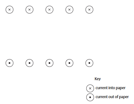
(i) Draw one field line on the diagram to show the direction of the magnetic field. (2)
(ii) Use the field line to determine which end of the solenoid is the north pole and label this on the diagram. (1)
(b) A transformer consists of two solenoids and an iron core.
This is the label on the transformer.
| Number of turns on primary coil: \(180\) |
| Number of turns on secondary coil: \(345\) |
| Output voltage: \(230\,\mathrm{V}\) |
| Output power: \(320\,\mathrm{W}\) |
(i) State the formula linking input (primary) voltage, output (secondary) voltage and the turns ratio. (1)
(ii) Calculate the input voltage of this transformer. (3)
input voltage = __________________ \(\mathrm{V}\)
(iii) Give the name of this type of transformer. (1)
(iv) When the transformer is in use, there is a current in the primary coil and in the secondary coil.
State the type of current in the coils of the transformer. (1)
Syllabus Topic Codes (Edexcel International GCSE Physics 4PH1):
• 6.17–6.18P: Transformers and Step-Up and Step-Down Transformers — parts (b)(iii) and (b)(iv)
• 6.19–6.20P: Transformer Voltage, Turns Ratio, and Power — parts (b)(i) and (b)(ii)
▶️ Answer/Explanation
(a)(i) Direction of the magnetic field [2 marks]
The current in the upper row is into the page and the current in the lower row is out of the page. Using the right-hand grip rule for the current in the solenoid, the magnetic field inside the solenoid is directed from right to left.
Therefore, a correct field line should be drawn through the solenoid without crossing the wires, with an arrow pointing from right to left inside the solenoid.
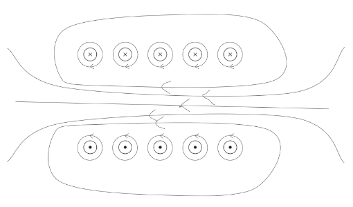
Final Answer: Draw a continuous magnetic field line with its arrow pointing from right to left through the solenoid.
(a)(ii) North pole of the solenoid [1 mark]
Magnetic field lines inside a solenoid point from the south pole to the north pole.
Since the field inside the solenoid is directed from right to left, the left-hand end is the north pole.
Final Answer: \( \boxed{\mathrm{Left\ end=N}} \)
(b)(i) Transformer equation [1 mark]
The relationship between voltage and number of turns is:
\(\dfrac{N_p}{N_s}=\dfrac{V_p}{V_s}\)
Final Answer: \( \boxed{\dfrac{N_p}{N_s}=\dfrac{V_p}{V_s}} \)
(b)(ii) Input voltage [3 marks]
1. Substitute the known values:
\(\dfrac{180}{345}=\dfrac{V_p}{230}\)
2. Rearrange for the primary voltage:
\(V_p=\dfrac{230\times180}{345}\)
3. Calculate:
\(V_p=120\,\mathrm{V}\)
Final Answer: \( \boxed{120\,\mathrm{V}} \)
(b)(iii) Type of transformer [1 mark]
The secondary coil has more turns than the primary coil:
\(345>180\)
Therefore, the transformer increases the output voltage and is a step-up transformer.
Final Answer: \( \boxed{\mathrm{Step\!-\!up\ transformer}} \)
(b)(iv) Type of current [1 mark]
A transformer operates using a changing magnetic field produced by an alternating current.
Therefore, the current in the coils is alternating current, or a.c.
Final Answer: \( \boxed{\mathrm{alternating\ current\ (a.c.)}} \)
Question
This question is about electromagnetism.
(a) Diagram 1 shows the magnetic field around a straight section of copper wire.

Explain why the copper wire has the magnetic field shown in the diagram.
(b) A student investigates how the strength of an electromagnet varies with the current in the electromagnet. The diagram shows their apparatus.

This is the student’s method.
- switch on the electromagnet at its maximum current
- place a load of \(100\,\mathrm{g}\) so that it is held above the floor by the electromagnet
- slowly reduce the current in the electromagnet until the load falls from the electromagnet
- record the current at which the load falls
- record the current at which the same load falls two more times
Repeat the method for loads of different masses.
(i) Suggest a suitable safety precaution for the student’s investigation.
(ii) The table shows the student’s results.

Calculate the mean current when the mass of the load was \(600\,\mathrm{g}\). Give your answer to a suitable number of significant figures.
(iii) On the grid, plot a graph of the mean current against the mass of the load. The scale for the mass axis has been done for you.
(iv) Draw the line of best fit.

(v) The student predicts that a load of \(1.0\,\mathrm{kg}\) will fall when the current in the electromagnet is \(3.0\,\mathrm{A}\). Comment on the student’s prediction.
Syllabus Topic Codes (Edexcel International GCSE Physics 4PH1):
• 6.9P: Construction of Electromagnets — parts (b), (i), (ii), (iii), (iv) and (v)
▶️ Answer/Explanation
(a) Magnetic field around a current-carrying wire [2 marks]
- There must be a current flowing through the copper wire.
- The current must be flowing to the right.
A current-carrying conductor produces a magnetic field around it. The direction of the magnetic field depends on the direction of the current.
(b)(i) Safety precaution [1 mark]
One suitable precaution is to keep hands and feet away from the load so that they are not hit when the load falls.
Other suitable precautions include taking care to avoid the heating effect of the current or protecting the floor from damage caused by falling loads.
(b)(ii) Mean current for \(600\,\mathrm{g}\) [2 marks]
Calculate the mean of the three current readings for the \(600\,\mathrm{g}\) load:
\(\mathrm{mean\ current}=\dfrac{\mathrm{sum\ of\ readings}}{3}\)
The calculated mean is:
\(\mathrm{mean\ current}=1.833\ldots\,\mathrm{A}\)
To \(3\) significant figures:
\(\boxed{1.83\,\mathrm{A}}\)
(b)(iii) Plotting the graph [3 marks]
- Use a sensible, continuous scale on the current axis so that the plotted data covers a significant portion of the grid.
- Label the vertical axis as current, \(I/\mathrm{A}\).
- Plot all the data points accurately using the calculated mean currents.

(b)(iv) Line of best fit [1 mark]
Draw a straight line of best fit through the data, with approximately equal numbers of points distributed on either side of the line.
(b)(v) Comment on the prediction [3 marks]
- \(1.0\,\mathrm{kg}=1000\,\mathrm{g}\).
- The trend in the results indicates that the current required increases as the mass of the load increases.
- The data suggests that current is approximately directly proportional to mass, so extrapolation may give a value close to \(3.0\,\mathrm{A}\).
- However, \(1000\,\mathrm{g}\) is outside the range of the masses tested, so the prediction involves extrapolation.
- The pattern observed within the measured range may not continue beyond the range of data collected.
Therefore, the prediction of \(3.0\,\mathrm{A}\) may be reasonable based on the trend, but it is less reliable because \(1.0\,\mathrm{kg}\) is outside the experimental range.
Question
This question is about magnetic fields.
(a) A student positions a thick wire vertically through the centre of a horizontal card. The student then passes a constant current through the wire in the downward direction, as shown in diagram 1.

(i) On diagram 1, draw the shape and direction of the magnetic field produced by the current in the wire.
(ii) Describe a method the student could use to show the shape of the magnetic field produced by the current in the wire.
(b) The student then removes the card and sets up a second wire next to the first wire, as shown in diagram 2.

The current in both wires is in the downward direction. The student observes that the wires move towards each other. Explain why the wires move towards each other.
Syllabus Topic Codes (Edexcel International GCSE Physics 4PH1):
• 6.6: Core Practical: Magnetic Field Patterns — part (a)(ii)
• 6.12–6.14: Force on a Current-Carrying Conductor and the Left-Hand Rule — part (b)
▶️ Answer/Explanation
(a)(i) Magnetic field around a current-carrying wire [3 marks]
The magnetic field consists of concentric circles centred on the wire and lying parallel to the plane of the card.
Because the current is in the downward direction, the direction of the magnetic field is clockwise when viewed from above.
The field can therefore be represented by at least two concentric circles with arrows showing a clockwise direction.

(a)(ii) Showing the magnetic field pattern [2 marks]
Method using iron filings:
- Place iron filings evenly on the card around the wire.
- Switch on the current and gently tap the card. The iron filings align with the magnetic field and show the circular field pattern.
Alternatively, a plotting compass can be moved to different positions around the wire to determine the direction of the magnetic field at each point.
(b) Force between the two current-carrying wires [3 marks]
- Each current-carrying wire produces a magnetic field around itself.
- Each wire is therefore carrying current while it is in the magnetic field produced by the other wire.
- A current-carrying conductor in a magnetic field experiences a force.
- The forces on the two wires are equal in magnitude and opposite in direction.
Since the currents in the two parallel wires are in the same direction, the magnetic forces act towards each other. Therefore, the wires move towards each other.
The direction can also be determined using the right-hand grip rule to find the magnetic field and the left-hand rule to determine the force on the second current-carrying wire.