CORE PRACTICAL 3: Determine the Young Modulus of a Material
This practical measures how much a material (usually a wire) extends when forces are applied, and uses stress–strain relationships to calculate the Young modulus.
Aim
To determine the Young modulus \( E \) of a material using the relationship:
$ E = \frac{\text{stress}}{\text{strain}} = \frac{F L_0}{A \Delta L} $
Apparatus
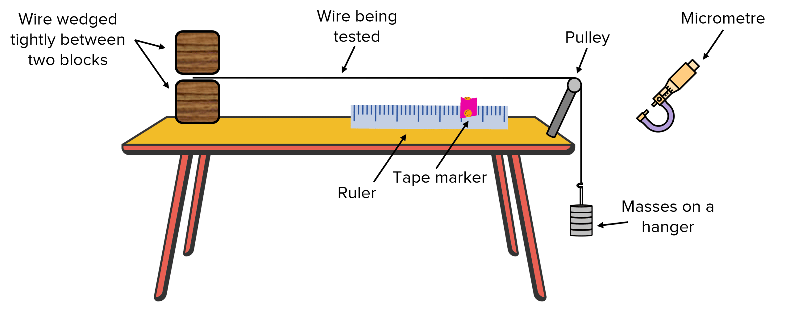
- Long test wire (e.g., nichrome)
- Micrometer screw gauge (to measure wire diameter)
- Metre ruler or measuring scale
- Clamps and stand
- Pointer attached to the wire
- Masses and mass hanger (to apply known force)
- Reference wire (to eliminate support movement)
- Vernier scale / travelling microscope (for precision)
Theory
The wire obeys:
$ \text{stress} = \frac{F}{A}, \quad \text{strain} = \frac{\Delta L}{L_0} $
So the Young modulus is:
$ E = \frac{F L_0}{A \Delta L} $
- \( F = mg \) is the applied force
- \( L_0 \) = original length of wire
- \( \Delta L \) = extension
- \( A = \pi r^2 \) = cross-sectional area
Procedure
- Measure diameter of wire at several points using a micrometer. Take an average radius \( r \).
- Secure the wire firmly at the top clamp. Attach a pointer at the bottom near the scale.
- Measure the initial length \( L_0 \) of the wire from the clamp to the pointer.
- Set up a second reference wire alongside to compensate for stand movement.
- Hang a mass hanger on the test wire and add masses gently.
- Record extension \( \Delta L \) for each added mass using the pointer scale.
- Repeat readings at least three times for accuracy.
- Plot a graph of F (y-axis) against extension ΔL (x-axis).
Data Processing
The graph should be linear in the elastic region.
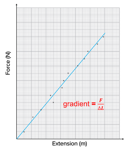
- The gradient gives stiffness \( k \):
\( k = \frac{F}{\Delta L} \)
- The Young modulus can be calculated using:
$ E = \frac{F L_0}{A \Delta L} $
Assumptions
- The wire obeys Hooke’s Law (within elastic limit).
- The wire is of uniform diameter.
- Temperature remains constant.
- No slipping occurs at the clamp.
- Extensions are small compared to original length.
Sources of Error
- Parallax error in reading pointer scale.
- Wire not perfectly vertical.
- Diameter of wire varies along its length.
- Wire may have initial kinks.
- Stand may move slightly (corrected using reference wire).
- Temperature changes can affect elasticity.
How to Improve Accuracy
- Use a travelling microscope to measure extension precisely.
- Use a long wire to reduce percentage errors in extension.
- Repeat diameter measurements in multiple orientations.
- Use small mass increments to avoid overshooting elastic limit.
- Plot a best-fit line on the F–ΔL graph.
Example
A 2.00 m wire of radius \( 0.25\, \mathrm{mm} \) extends by \( 0.75\, \mathrm{mm} \) when a mass of \( 1.50\, \mathrm{kg} \) is added. Calculate the Young modulus.
▶️ Answer / Explanation
Cross-sectional area:
\( A = \pi r^2 = \pi (0.00025)^2 = 1.96\times10^{-7}\, \mathrm{m^2} \)
Force applied:
\( F = mg = 1.50 \times 9.8 = 14.7\, \mathrm{N} \)
Extension:
\( \Delta L = 0.75\,\mathrm{mm} = 7.5\times10^{-4}\,\mathrm{m} \)
Substitute into formula:
$ E = \frac{F L_0}{A \Delta L} = \frac{14.7 \times 2.00}{(1.96\times10^{-7})(7.5\times10^{-4})} $
\( E \approx 2.0\times10^{11}\, \mathrm{Pa} \)