Principles of a Potential Divider Circuit and Calculating Voltages & Resistances
A potential divider is a circuit that splits an input voltage into smaller, precise voltages. It uses resistors in series to produce a predictable ratio of the total voltage.
It is one of the most important circuits in electronics.
Basic Potential Divider Circuit
Two resistors \( R_1 \) and \( R_2 \) are connected in series across a supply voltage \( V_{\text{in}} \):
- Current is the same through both resistors.
- The total voltage is shared between them.
- The voltage across each resistor depends on its resistance.
Formula for Output Voltage
If the output voltage is taken across \( R_2 \):
\( V_{\text{out}} = V_{\text{in}} \dfrac{R_2}{R_1 + R_2} \)
This is the standard potential divider equation.
Similarly, voltage across \( R_1 \):
\( V_1 = V_{\text{in}} \dfrac{R_1}{R_1 + R_2} \)
Understanding the Physics
- Larger resistance → larger share of the voltage.
- Resistors in series divide voltage in proportion to their resistance values.
- Current is determined by the total resistance:
\( I = \dfrac{V_{\text{in}}}{R_1 + R_2} \)
- This directly affects \( V_1 = IR_1 \) and \( V_2 = IR_2 \).
Variable Potential Divider (Potentiometer)
A sliding contact (wiper) moves along a uniform resistive wire:
- Moving the wiper changes the ratio \( \dfrac{R_2}{R_1 + R_2} \).
- This gives a continuously variable output voltage.
- Used in volume controls, sensors, and calibration circuits.
Potential Divider as a Sensor Circuit
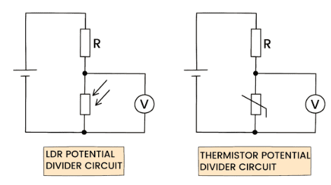

Using LDRs or thermistors:
- Resistance changes with light or temperature.
- Thus the output voltage changes automatically.
- Used in automatic night lights, thermostats, etc.
How to Calculate Voltages in a Potential Divider
Given \( R_1 \), \( R_2 \), and \( V_{\text{in}} \):
- Calculate total resistance:
\( R_{\text{total}} = R_1 + R_2 \)
- Find current in the circuit:
\( I = \dfrac{V_{\text{in}}}{R_{\text{total}}} \)
- Calculate voltage across each resistor:
\( V_1 = IR_1 \), \( V_2 = IR_2 \)
- Alternatively use divider equation directly.
How to Calculate Resistance from a Known Output Voltage
If \( V_{\text{out}} \), \( V_{\text{in}} \), and one resistor are known:
From \( V_{\text{out}} = V_{\text{in}} \dfrac{R_2}{R_1 + R_2} \)
Rearrange to make \( R_2 \) or \( R_1 \) the subject.
To find \( R_2 \):
\( R_2 = \dfrac{V_{\text{out}} R_1}{V_{\text{in}} – V_{\text{out}}} \)
To find \( R_1 \):
\( R_1 = \dfrac{(V_{\text{in}} – V_{\text{out}}) R_2}{V_{\text{out}}} \)
Example (Easy)
A potential divider has \( R_1 = 2\ \mathrm{k\Omega} \), \( R_2 = 2\ \mathrm{k\Omega} \), and input voltage \( 10\ \mathrm{V} \). Find the output voltage across \( R_2 \).
▶️ Answer / Explanation
Using \( V_{\text{out}} = V_{\text{in}} \dfrac{R_2}{R_1 + R_2} \)
\( V_{\text{out}} = 10 \cdot \dfrac{2}{2 + 2} = 10 \cdot \dfrac{2}{4} = 5\ \mathrm{V} \)
Example (Medium)
A potential divider has input voltage \( 12\ \mathrm{V} \). A thermistor (as \( R_2 \)) has resistance \( 5\ \mathrm{k\Omega} \) at low temperature and \( 500\ \Omega \) at high temperature. \( R_1 = 3\ \mathrm{k\Omega} \). Calculate \( V_{\text{out}} \) at low and high temperature.
▶️ Answer / Explanation
Low temperature:
\( V_{\text{out}} = 12 \dfrac{5000}{3000 + 5000} = 12 \dfrac{5000}{8000} = 7.5\ \mathrm{V} \)
High temperature:
\( V_{\text{out}} = 12 \dfrac{500}{3000 + 500} = 12 \dfrac{500}{3500} \approx 1.71\ \mathrm{V} \)
Thus the output voltage decreases as temperature increases (NTC thermistor).
Example (Hard)
A potential divider produces \( 3.0\ \mathrm{V} \) from a \( 12\ \mathrm{V} \) supply. If \( R_1 = 1.2\ \mathrm{k\Omega} \), find \( R_2 \).
▶️ Answer / Explanation
Use:
\( R_2 = \dfrac{V_{\text{out}}R_1}{V_{\text{in}} – V_{\text{out}}} \)
\( R_2 = \dfrac{3.0 \times 1200}{12 – 3.0} = \dfrac{3600}{9} = 400\ \Omega \)
Analysing Potential Divider Circuits with Variable Resistors, Thermistors (NTC) and LDRs
In a potential divider, replacing one resistor with a variable resistor, a thermistor, or an LDR allows the output voltage to change automatically with temperature or light. This principle is widely used in sensor and control circuits.
Recap: Potential Divider Equation
For two resistors \( R_1 \) and \( R_2 \) in series across \( V_{\text{in}} \), with output across \( R_2 \):
\( V_{\text{out}} = V_{\text{in}} \dfrac{R_2}{R_1 + R_2} \)
This formula applies even if \( R_2 \) (or \( R_1 \)) is variable.
Using a Variable Resistor

- As the slider moves, the resistance changes.
- This changes the ratio \( \dfrac{R_2}{R_1 + R_2} \).
- Thus, the output voltage is adjustable.
Key idea: Increasing \( R_2 \) → increases \( V_{\text{out}} \). Decreasing \( R_2 \) → decreases \( V_{\text{out}} \).
Using a Thermistor (NTC)
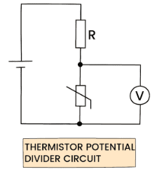
- NTC thermistor: resistance decreases as temperature increases.
- Place the thermistor as \( R_2 \) if you want \( V_{\text{out}} \) to decrease with temperature.
- Place the thermistor as \( R_1 \) if you want \( V_{\text{out}} \) to increase with temperature.
Case 1: Thermistor as \( R_2 \)
- Cold → large \( R_T \) → large \( V_{\text{out}} \)
- Hot → small \( R_T \) → small \( V_{\text{out}} \)
Case 2: Thermistor as \( R_1 \)
- Cold → large \( R_1 \) → small \( V_{\text{out}} \)
- Hot → small \( R_1 \) → large \( V_{\text{out}} \)
Used in: thermostats, temperature sensors, fire alarms.
Using an LDR
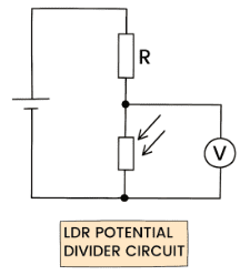
- LDR resistance decreases as light intensity increases.
- Place the LDR as \( R_2 \): light increases → \( R_2 \) decreases → \( V_{\text{out}} \) decreases.
- Place the LDR as \( R_1 \): light increases → \( R_1 \) decreases → \( V_{\text{out}} \) increases.
Used in: automatic street lights, light sensors, security circuits.
Summary: How the Output Voltage Changes
| Component | Position | Condition | Effect on \( V_{\text{out}} \) |
|---|---|---|---|
| Thermistor (NTC) | As \( R_2 \) | Hot (low R) | Decreases |
| Thermistor (NTC) | As \( R_1 \) | Hot (low R) | Increases |
| LDR | As \( R_2 \) | Bright (low R) | Decreases |
| LDR | As \( R_1 \) | Bright (low R) | Increases |
Example (Easy)
A thermistor is placed as \( R_2 \) in a potential divider. What happens to the output voltage as temperature increases?
▶️ Answer / Explanation
- Temperature ↑ → resistance of thermistor ↓
- So ratio \( \dfrac{R_2}{R_1 + R_2} \) decreases
- Therefore \( V_{\text{out}} \) decreases
Example (Medium)
An LDR is used as \( R_1 \) in a potential divider with \( V_{\text{in}} = 9\ \mathrm{V} \). In bright light, \( R_1 = 500\ \Omega \) and \( R_2 = 1500\ \Omega \). Find \( V_{\text{out}} \).
▶️ Answer / Explanation
\( V_{\text{out}} = 9 \dfrac{R_2}{R_1 + R_2} = 9 \dfrac{1500}{500 + 1500} = 9 \dfrac{1500}{2000} = 6.75\ \mathrm{V} \)
Because light reduces \( R_1 \), more voltage appears across \( R_2 \).
Example (Hard)
A potential divider is used as a temperature sensor with thermistor as \( R_1 \) and fixed resistor \( R_2 \). At low temperature, \( R_1 = 8\ \mathrm{k\Omega} \). At high temperature, \( R_1 = 1.2\ \mathrm{k\Omega} \). If \( R_2 = 3\ \mathrm{k\Omega} \) and \( V_{\text{in}} = 10\ \mathrm{V} \), calculate \( V_{\text{out}} \) at low and high temperature.
▶️ Answer / Explanation
Low temperature:
\( V_{\text{out}} = 10 \dfrac{R_2}{R_1 + R_2} = 10 \dfrac{3000}{8000 + 3000} = 10 \dfrac{3000}{11000} = 2.73\ \mathrm{V} \)
High temperature:
\( V_{\text{out}} = 10 \dfrac{3000}{1200 + 3000} = 10 \dfrac{3000}{4200} = 7.14\ \mathrm{V} \)
Conclusion: As temperature increases, thermistor resistance falls → \( V_{\text{out}} \) rises sharply.