Question
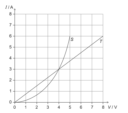
Two conductors S and T have the V/I characteristic graphs shown below.
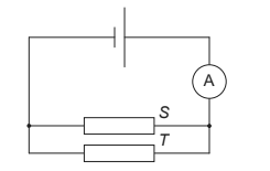
When the conductors are placed in the circuit below, the reading of the ammeter is 6.0 A.
What is the emf of the cell?
A 4.0 V
B 5.0 V
C 8.0 V
D 13 V
▶️Answer/Explanation
Ans: A
The equation \(V=iR\) is the defining equation for resistance, and it applies to all conducting devices, whether they obey Ohm’s law or not. If we measure the potential difference \(V \) across, and the current \(i\) through, any device, even a pn junction diode, we can find its resistance at that value of \(V\) as \(R=\frac{V}{i}\)
\(\frac{1}{R_T}=\frac{6-0}{8-0}=\frac{3}{4}\)
From the graph , V and I is not defined for V equal 8 0r 13 hence these can not be correct options.
If emf = 5 V
Then from graph we have
\(\frac{1}{R_S} =\frac{6}{5}\)
hence
\(\frac{1}{R} =\frac{1}{R_S} +\frac{1}{R_T} =\frac{6}{5}+\frac{6}{8} =1.95\)
\(i=v \times \frac{1}{R} =5\times 1.95 =9.75 \neq 6\)
but current is 6 A hence this can not be correct option
Now verify for emf = \(4v\)
\(\frac{1}{R_S} =\frac{3}{4}\)
\(\frac{1}{R_T} =\frac{6}{8}\)
\(\frac{1}{R} =\frac{1}{R_S} +\frac{1}{R_T} =\frac{3}{4}+\frac{6}{8} =\frac{3}{2}\)
\(i=v \times \frac{1}{R} =4\times \frac{3}{2} =6 \)
which is true as given current is 6 A. Hence correct option is A
Question
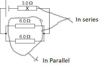
A cell of emf 6.0 V and negligible internal resistance is connected to three resistors as shown.
The resistors have resistance of 3.0 Ω and 6.0 Ω as shown.
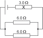
What is the current in resistor X?
A. 0.40 A
B. 0.50 A
C. 1.0 A
D. 2.0 A
▶️Answer/Explanation
Markscheme
C
\(\frac{1}{R_1} =\frac{1}{6}+\frac{1}{6} =\frac{2}{6}\)
\(\therefore R_1 =3\)
\(R_{eq} = 3+3 = 6\)
\(i =\frac{V}{R_{eq}} =\frac{6}{6} = 1\;A\)
Question
A circuit consists of a cell of electromotive force (emf) 6.0V and negligible internal resistance connected to two resistors of 4.0Ω.
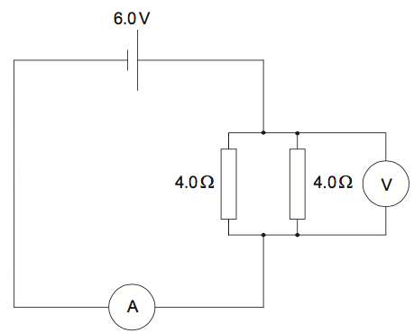
The ammeter has resistance equal to 1.0Ω and the voltmeter is ideal. What are the readings of the ammeter and the voltmeter?
▶️Answer/Explanation
Markscheme
C
\(\frac{1}{R_{1}}=\frac{1}{4}+\frac{1}{4}=\frac{2}{4}\)
\(R_{1} =2 \; \Omega\)
\(R_{eq} = 2 + 1 = 3\;\Omega\)
\(i = \frac{V}{R_{eq}} =\frac{6}{3}= 2\:A\)
Hence reading in Ammeter reading \( = 2\:A\)
Reading across \(V = 6 -ir_{internal}= 6-2\times 1= 4V\)
Question
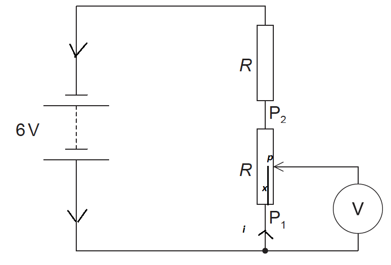
The diagram shows an electric circuit containing a potentiometer of maximum resistance R. The potentiometer is connected in series with a resistor also of resistance R. The electromotive force (emf) of the battery is 6 V and its internal resistance is negligible.
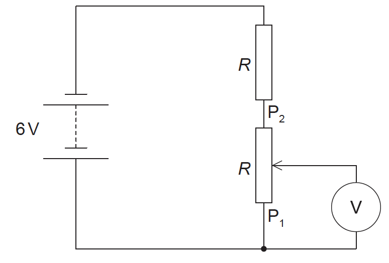
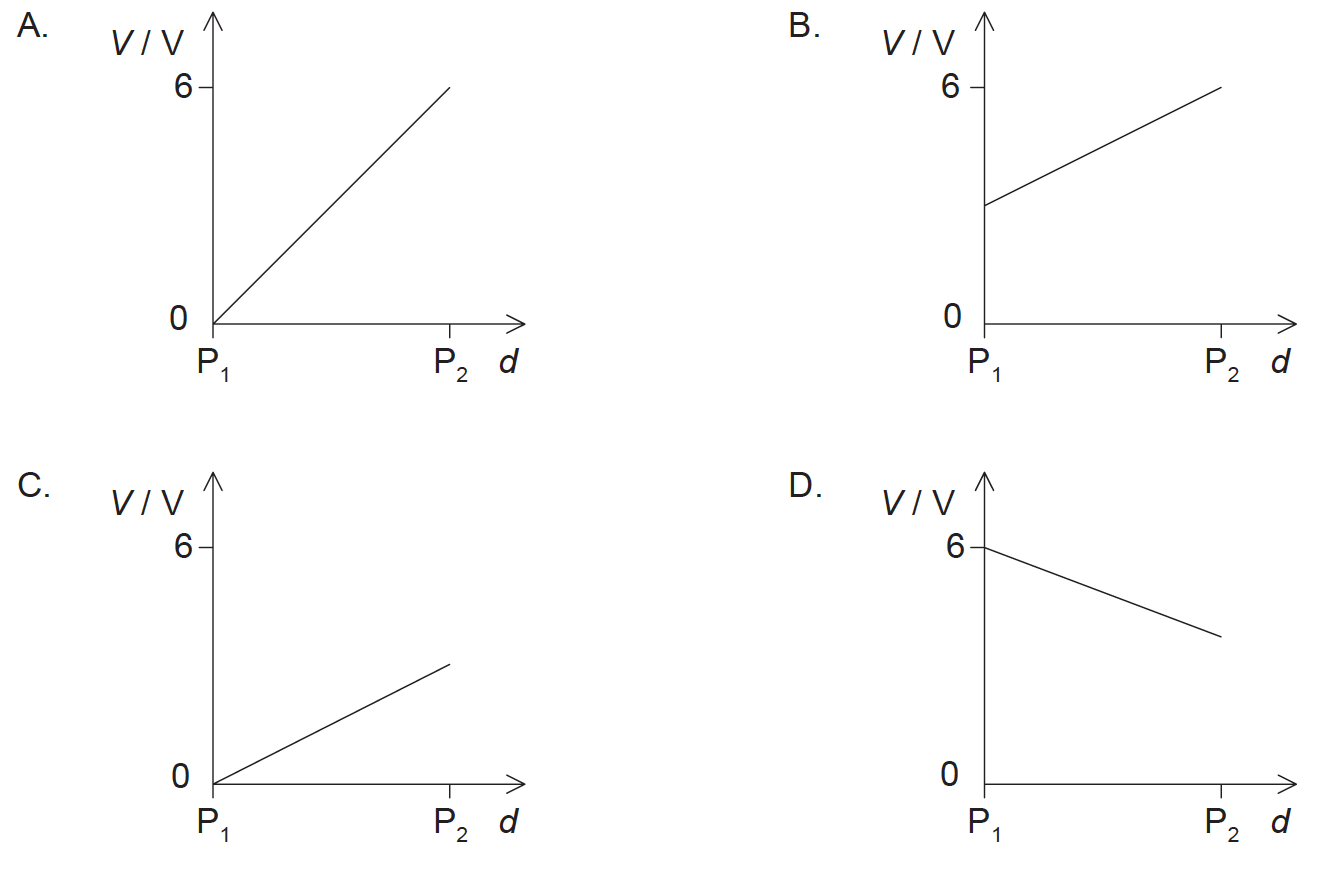
The slider on the potentiometer is moved from P1 to P2. Which graph shows the variation of the voltmeter V reading with slider distance d?
▶️Answer/Explanation
Markscheme
C
As the wire is uniform, the resistance of a piece of the wire is proportional to its length. Hence, the potential difference across a piece of wire is also proportional to its length .
Let resistance per unit length of potentiometer be \(R_0\)
Hence Resistance for \(P_1p = R_0 \times x\)
Also
\(i=\frac{6}{R+R}=\frac{6}{2R}\)
Voltmeter reading \(= V_x = i\times R_x\)
\(V_x =\frac{6}{2R} \times R_x\)
But \( R_x= R_0 \times x \)
\(\therefore V_x =\frac{6}{2R} \times R_0 \times x =V_0 x\)
\(or\)
\(\frac{V_x}{V_0}=x .\)
This is straight line passing through origin.
Also maximum reading of \(V \), when point p moves to\( P_2\)
Hence at point \( P_2 \), the reading is maximum but it has to be less than 6 V as total emf of circuit is 6 volt, hence correct option in C not A
Question
A filament lamp and a semiconducting diode have the voltage–current (\(V\)–\(I\)) characteristics shown and are connected in parallel.
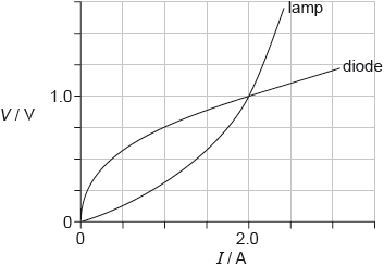
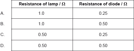
What is the resistance of the lamp and the resistance of the diode when the current in each device is 2.0 A?
▶️Answer/Explanation
Markscheme
D
The equation \(V=iR\) is the defining equation for resistance, and it applies to all conducting devices, whether they obey Ohm’s law or not. If we measure the potential difference \(V \) across, and the current \(i\) through, any device, even a pn junction diode, we can find its resistance at that value of \(V\) as \(R=\frac{V}{i}\)
From the graph , we can see that at I= 2 A , voltage for both lamp and diode is same 1 V
Hence Resistance for both is
\(R = \frac{V}{I} =\frac{1}{2}=0.5 \; \Omega\)