Electric circuits
∙An electric circuit is a set of conductors (like wires) and components (like resistors, lights, etc.) connected to an electrical voltage source (like a cell or a battery) in such a way that current can flow in complete loops.
∙Here are two circuits consisting of cells, resistors, and wires.
∙Note current flowing from (+) to (-) in each circuit.

A complete circuit will always contain a cell or a battery.
∙The schematic diagram of a cell is this:

![]()
∙A battery is just a group of cells connected in series:

∙If each cell is 1.5 V, then the battery above is 3(1.5) = 4.5 V. What is the voltage of your calculator battery?
∙A fixed-value resistor looks like this:

∙The schematic of a fixed-value resistor looks like this:
EXAMPLE:
Draw schematic diagrams of each of the following circuits:

▶️Answer/Explanation
Solution:

Investigating combinations of resistors in series
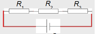
∙Resistors can be connected to one another in series, which means one after the other.
∙Note that there is only one current I and that I is the same for all series components.
$\text{Conservation of energy tells us } q\varepsilon = qV_1 + qV_2 + qV_3.$
$\text{Thus, } \varepsilon = IR_1 + IR_2 + IR_3 \text{ from Ohm’s law } V = IR.$
$\varepsilon = I(R_1 + R_2 + R_3) \quad \text{(factoring out } I\text{)}$
$\varepsilon = I R, \quad \text{where } R = R_1 + R_2 + R_3.$

EXAMPLE:
Three resistors of 330 Ω each are connected to a 6.0 V battery in series.
(a) What is the circuit’s equivalent resistance?
(b) What is the current in the circuit?
▶️Answer/Explanation
SOLUTION:
(a) In series,
\[
R = R_1 + R_2 + R_3
\]
so that
\[
R = 330 + 330 + 330 = 990 \, \Omega.
\]
(b) Since the voltage on the entire circuit is 6.0 V, and since the total resistance is 990 Ω, from Ohm’s law we have
\[
I = \frac{V}{R} = \frac{6}{990} = 0.0061 \, A.
\]
Investigating combinations of resistors in parallel
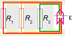
- Resistors can also be in parallel.
- In this circuit, each resistor is connected directly to the cell.
- Thus, each resistor has the same voltage \( V \) and V is the same for all parallel components.
- From \( \varepsilon = V_1 = V_2 = V_3 \equiv V \) and
- $\frac{\varepsilon}{R} = \frac{V_1}{R_1} + \frac{V_2}{R_2} + \frac{V_3}{R_3}$
- we get
- $\frac{V}{R_1} = \frac{V}{R_1} + \frac{V}{R_2} + \frac{V}{R_3}$
- Thus, the equivalent resistance \( R \) is given by

EXAMPLE:
Three resistors of 330 Ω each are connected to a 6.0 V cell in parallel .
(a) What is the circuit’s resistance?
(b) What is the voltage on each resistor?
▶️Answer/Explanation
SOLUTION:
(a) In parallel,
\[
\frac{1}{R} = \frac{1}{R_1} + \frac{1}{R_2} + \frac{1}{R_3}
\]
so that
\[
\frac{1}{R} = \frac{1}{330} + \frac{1}{330} + \frac{1}{330} = 0.00909
\]
\[
\Rightarrow R = \frac{1}{0.00909} = 110 \, \Omega.
\]
(b) The voltage on each resistor is 6.0 V, since the resistors are in parallel. (Each resistor is clearly directly connected to the battery).
Ideal voltmeters – ∞ Ω resistance
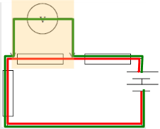
∙Voltmeters are connected in parallel.
∙The voltmeter reads the voltage of only the component it is in parallel with.
∙The green current represents the amount of current the battery needs to supply to the voltmeter in order to make it register.
∙The red current is the amount of current the battery supplies to the original circuit.
∙In order to NOT ALTER the original properties of the circuit, ideal voltmeters have extremely high resistance (∞ Ω) to minimize the green current.
Ideal ammeters – 0 Ω resistance
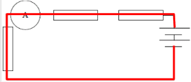
∙Ammeters are connected in series.
∙The ammeter is supposed to read the current of the original circuit.
∙In order to NOT ALTER the original properties of the circuit, ideal ammeters have extremely low resistance (0 Ω) to minimize the effect on the red current.
Example:
A 12 V battery is connected in series with a resistor of \( 6.0 \, \Omega \). An ideal voltmeter is connected across the resistor. What is the reading on the voltmeter?
▶️ Answer/Explanation
Given:
Battery voltage = \( 12 \, \text{V} \)
Resistor = \( 6.0 \, \Omega \)
Only one resistor, so all voltage drops across it.
Using Ohm’s Law:
\( V = IR \Rightarrow I = \frac{V}{R} = \frac{12}{6.0} = 2.0 \, \text{A} \)
Voltage across the resistor (same as across voltmeter):
Since it’s the only component, the full 12 V is across it. Hence,
\( \boxed{V = 12 \, \text{V}} \)
The ideal voltmeter reads the full battery voltage of 12 V.