iGCSE Physics (0625) 4.3.1 Circuit diagrams and circuit components Paper 3 -Exam Style Questions- New Syllabus
Question
A student connects the electrical circuit shown in Fig. 9.1.
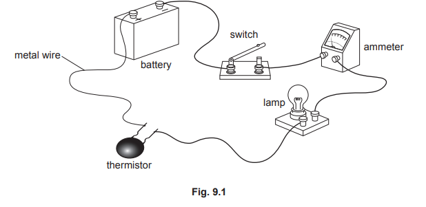
(a) Fig. 9.2 shows part of the circuit diagram for the circuit in Fig. 9.1. 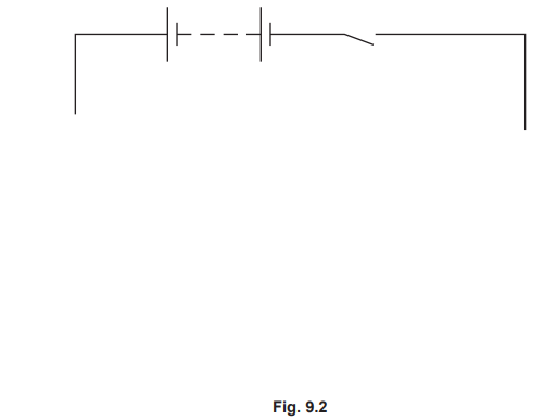
Complete the circuit diagram in Fig. 9.2 to represent the circuit in Fig. 9.1. Use standard electrical symbols.
(b) The potential difference across the lamp is 5.4V and the current in the lamp is 0.20A.
(i) Calculate the resistance of the lamp.
(ii) The lamp is switched on for 30s. Calculate the energy transferred in the lamp during this time.
(c) The student increases the temperature of the thermistor. State and explain what happens to the current in the circuit
Most-appropriate topic codes (Cambridge IGCSE Physics 0625):
• Topic 4.3.1 — Circuit diagrams and circuit components (Part (a))
• Topic 4.2.4 — Resistance (Part (b)(i))
• Topic 4.2.5 — Electrical energy and electrical power (Part (b)(ii))
• Topic 4.2.4 — Resistance (Part (c))
▶️ Answer/Explanation
(a)
correct symbol for:
ammeter
lamp
thermistor
symbols connected in series circuit
The circuit diagram must be completed by adding the correct standard electrical symbols for the ammeter, lamp, and thermistor, ensuring they are connected in a single series loop as shown in the physical circuit layout of Fig. 9.1.
(b)(i)
27 \((\Omega)\)
5.4 ÷ 0.2(0)
(R=) V ÷ I OR V = \(I \times R\) or in any form
Resistance is calculated using the equation \(R = \frac{V}{I}\). Substituting the given values of potential difference (5.4 V) and current (0.20 A) into the formula yields \(R = \frac{5.4}{0.20} = 27 \, \Omega\).
(b)(ii)
32 (J)
(E =) \(5.4 \times 0.2 \times 30\)
(E=) VIt OR \(P \times t\) OR \(I^2 \times R \times t\)
The energy transferred is determined using \(E = VIt\). Substituting the potential difference (5.4 V), current (0.20 A), and time (30 s) into the equation gives \(E = 5.4 \times 0.20 \times 30 = 32.4 \, \text{J}\), which rounds to 32 J.
(c)
current increases
(because) resistance (of thermistor) decreases
A thermistor is a temperature-dependent resistor with a negative temperature coefficient (NTC). As its temperature increases, its resistance significantly decreases, which reduces the total resistance of the series circuit and causes the current to increase according to Ohm’s law.