Question
(a) Fig. 11.1 shows in each of the diagrams a current-carrying conductor and a magnetic field pattern.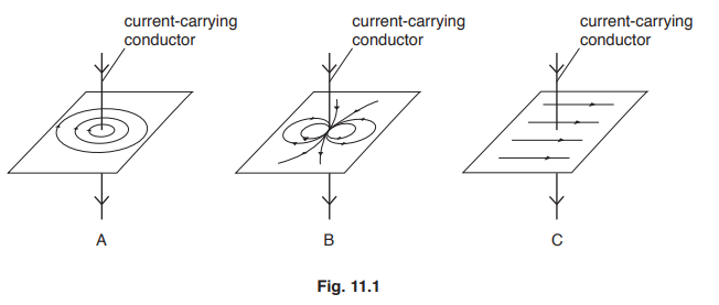
State the diagram which correctly shows the magnetic field around a current-carrying conductor.
(b) Fig. 11.2 shows three pieces of equipment.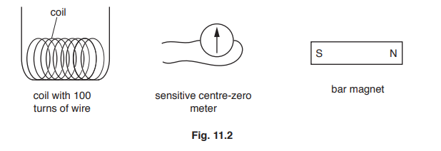
i. Describe how to generate and detect an electromotive force (e.m.f.) using the equipment in Fig. 11.2.
You may draw a diagram.
ii. Describe two changes that will generate a larger e.m.f. using similar equipment to that in Fig. 11.2.
(c) A student connects a lamp and centre-zero galvanometer in series with a generator, as shown in Fig. 11.3.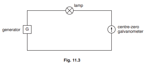
The student observes the galvanometer needle moving from side-to-side repeatedly.
Explain why the needle moves in this way.
Answer/Explanation
Answer:
(a) (diagram) A
(b) (i) connect coil to (centre zero) meter
move magnet in OR / AND out of coil
(observe) deflection on meter
(ii) any two from:
use stronger magnet
move magnet faster
more turns on coil OR use more than 100 turns
(c)
Question
Fig. 10.1 shows a coil of wire rotating steadily in the magnetic field between the poles of a
permanent magnet. The current generated in the coil is to pass through resistor R.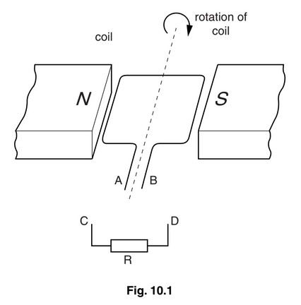
(a) The apparatus in Fig. 10.1 is part of an a.c. generator. What is connected between the ends A
and B of the coil and the connections C and D?
(b) (i) On Fig. 10.2, sketch a graph to show the variation with time of the current through R.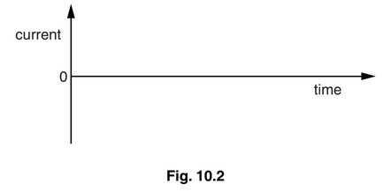
(ii) On Fig. 10.2, show the time T corresponding to one complete rotation of the coil.
(iii) State two ways in which the graph would be different if the coil spins at a faster rate.
1.
2.
(c) Suggest what could be connected between C and R so that the current in R is always in the
same direction.
Answer/Explanation
Answer:
(a) slip-rings (and brushes)
(b) (i) sinusoidal curve, any value at t = 0
(ii) appropriate T value indicated on graph
(iii) smaller T/ time of one cycle OR higher frequency
higher maximum current/ greater amplitude/higher peaks / higher peak-to-peak
(c) diode/rectifier