iGCSE Physics (0625) 4.5.5 The D.C. Motor Paper 3 -Exam Style Questions- New Syllabus
Question
(a) Fig. 9.1 represents part of a d.c. electric motor. The coil of wire rotates at a steady speed.
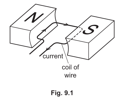
State two ways to make the coil rotate faster.
(b) Fig. 9.2 shows an electric fan.
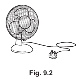
The electric motor for the fan requires 120 V a.c. The mains voltage is 220 V a.c.
A transformer steps down the mains voltage as shown in Fig. 9.3.
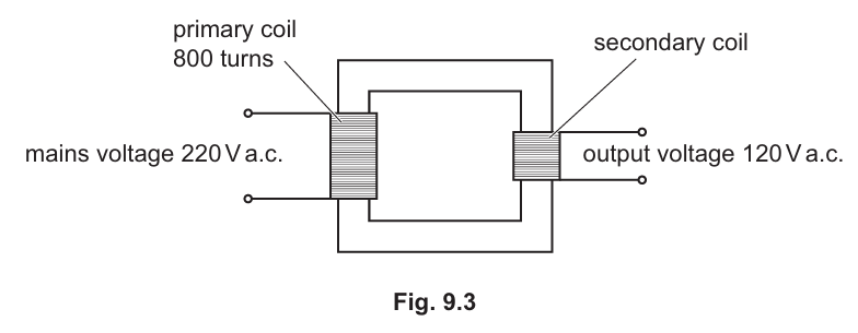
Calculate the number of turns on the secondary coil. Use the information in Fig. 9.3.
(c) A plug connects the transformer to the mains supply. There is a fuse in the plug.
Describe how a fuse works.
Most-appropriate topic codes (Cambridge IGCSE Physics 0625):
• Topic 4.5.5 — The d.c. motor (Part (a))
• Topic 4.5.6 — The transformer (Part (b))
• Topic 4.4 — Electrical safety (Part (c))
▶️ Answer/Explanation
(a)
For the correct answer:
any two from:
• increase (battery) voltage OR larger current in coil
• increase strength of magnet(ic) field OR strong(er) magnet
• increase number of turns (in coil)
The turning effect (torque) on the coil in a d.c. motor increases when either the current, the magnetic field strength, or the number of turns on the coil is increased. A larger current creates a stronger force on the wire, a stronger magnetic field exerts a greater force, and more turns means the force is multiplied across a longer length of wire, all resulting in faster rotation.
(b)
For the correct answer:
440 turns
Using the transformer equation $\frac{V_{\mathrm{p}}}{V_{\mathrm{s}}} = \frac{N_{\mathrm{p}}}{N_{\mathrm{s}}}$, where $V_{\mathrm{p}} = 220\, \mathrm{V}$, $V_{\mathrm{s}} = 120\, \mathrm{V}$, and $N_{\mathrm{p}} = 800$ turns. Rearranging for $N_{\mathrm{s}}$ gives $N_{\mathrm{s}} = N_{\mathrm{p}} \times \frac{V_{\mathrm{s}}}{V_{\mathrm{p}}} = 800 \times \frac{120}{220} \approx 436.36$. Rounding to the nearest whole number of turns yields $440$ turns (or $436$ depending on strict rounding). The calculation demonstrates the step-down relationship between primary and secondary coils.
(c)
For the correct answer:
any two from:
• large current (in fuse)
• (causes) fuse to melt
• isolating appliance from supply OR prevents/stops current in appliance
A fuse contains a thin metal wire designed to melt and break the circuit if the current exceeds a safe level. When a fault causes a large surge of current, the wire heats up rapidly due to its resistance, melts, and creates an open circuit. This disconnects the appliance from the mains supply, preventing overheating, damage to the appliance, or potential electrical fires.