Question
Diagram 1 shows a coil of wire $P$ between the poles of a magnet. The ends of coil $P$ are connected to a battery by slip rings.
Diagram 2 shows a coil of wire $Q$ between the poles of a different magnet. The ends of coil $Q$ are connected to a battery by a split-ring commutator.
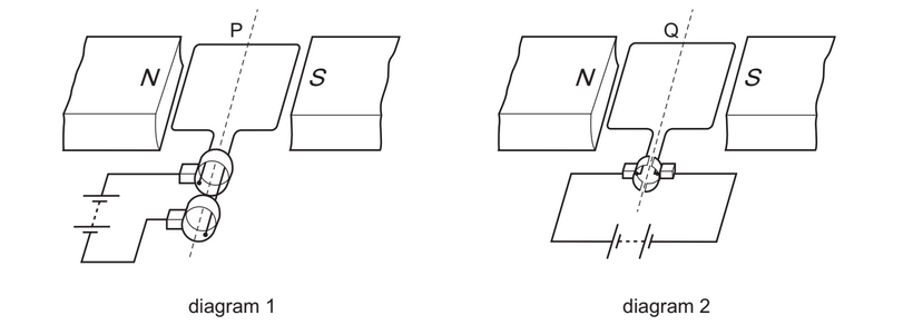
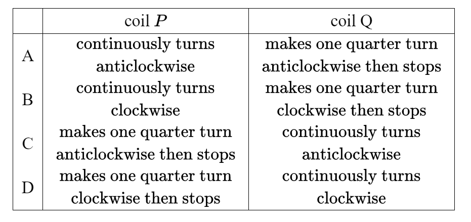
What happens to coils $P$ and $Q$ ?
Answer/Explanation
Ans:C
Question
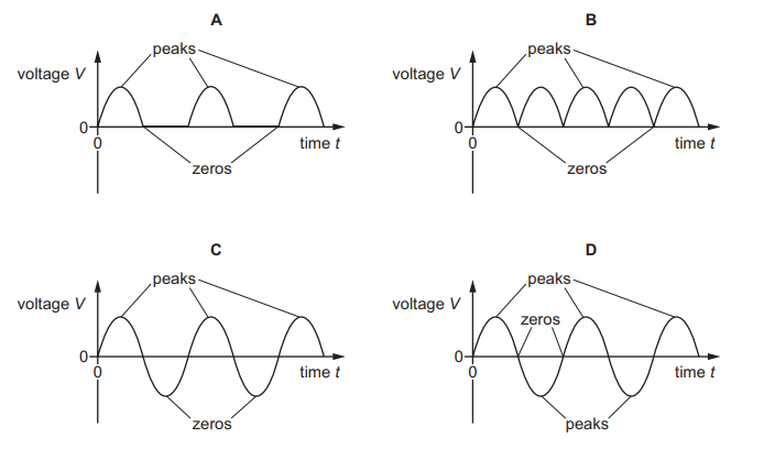
Which graph shows the voltage output of an a.c. generator with the peaks and zeros correctly labelled?
Answer/Explanation
Ans: D
Question
The diagram shows an a.c. generator.
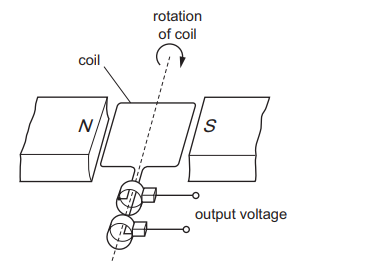
As the coil passes through the position shown, the output voltage is +10 V.
When does the output voltage become –10 V?
A. when the coil has turned through 90°
B. when the coil has turned through 180°
C. when the coil has turned through 270°
D. when the coil has turned through 360°
Answer/Explanation
Ans: B
Question
Which graph shows how the voltage of a simple a.c. generator varies with time? 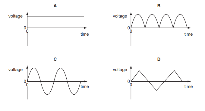
Answer/Explanation
Ans: C
