
CIE iGCSE Co-Ordinated Science P4.3.1 Circuit diagrams and circuit components Exam Style Questions Paper 4
Question
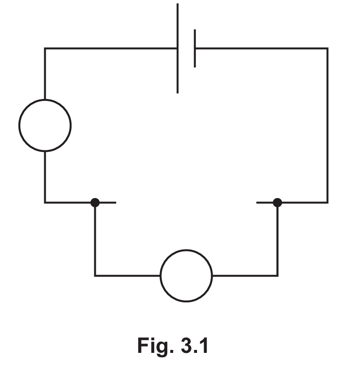
The student also connects a voltmeter to measure the potential difference across the thermistor.
Fig. 3.1 shows an incomplete circuit diagram of the circuit used by the student.
Calculate the charge that flows through the thermistor in \(60\,\text{s}\).
State the unit for your answer.
The student records the values shown by the ammeter and the voltmeter as the temperature of the thermistor increases.
Describe how the power output of the thermistor changes as the temperature of the thermistor increases.
Most-appropriate topic codes (Cambridge IGCSE Co-ordinated Sciences 0654, 2025–2027 syllabus):
• Topic P4.3.1 — Circuit diagrams and circuit components (Part (a)(i))
• Topic P4.2.2 — Electric current (Part (a)(ii))
• Topic P4.2.5 — Electrical energy and electrical power (Part (b))
• Topic P4.2.4 — Resistance (Part (c))
▶️ Answer/Explanation
(a)(i) Thermistor symbol added in series; ammeter and voltmeter correctly placed
The thermistor symbol must be drawn in the main series loop with the cell and ammeter.
The voltmeter must be connected in parallel across the thermistor only.
(a)(ii) \(180\,\text{C}\)
Charge is calculated using \(Q = It\).
\(Q = 3.0 \times 60 = 180\,\text{C}\) (coulombs).
(b) Power increases as temperature increases
As temperature rises, the resistance of the NTC thermistor decreases.
A lower resistance at constant voltage causes the current through the thermistor to increase.
Since \(P = IV\), an increase in current (with p.d. roughly maintained) means the power output increases.
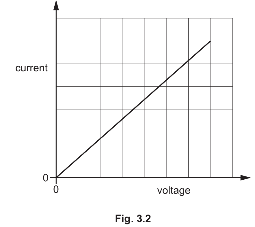
(c) Straight line through the origin
The graph is a straight line passing through the origin, showing current is directly proportional to voltage.
This means the resistance of the component stays constant, which is the definition of an ohmic conductor obeying Ohm’s law.
Question
Most-appropriate topic codes (Cambridge IGCSE Co-ordinated Sciences 0654):
• Topic P4.3.1 — Circuit diagrams and circuit components (Part (a))
• Topic P4.2.1 — Electrical charge (Part (a)(i))
• Topic P1.6.1 — Energy (Part (b))
▶️ Answer/Explanation
(a)(i) 8.0 Ω
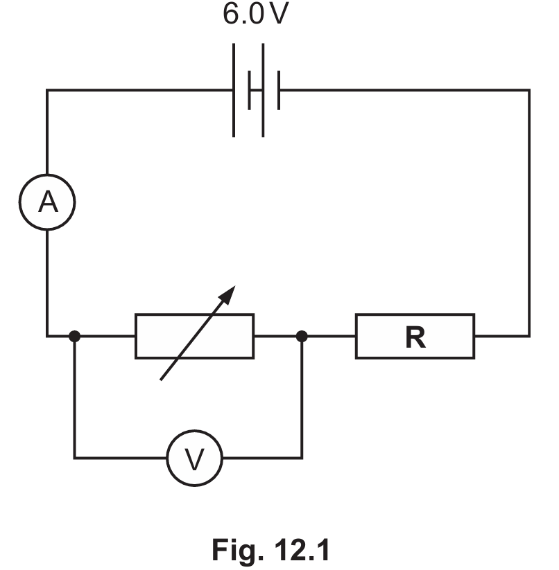
Since the battery, variable resistor and \(R\) are in series, the voltage across \(R\) \(= 6.0 – 2.0 = 4.0\) V.
Using \(R = \dfrac{V}{I} = \dfrac{4.0}{0.50} = 8.0\) Ω.
(a)(ii) Increase the resistance of the variable resistor to decrease the current flowing through R
Since the variable resistor is in series with \(R\), increasing its resistance reduces the total current in the circuit.
A lower current through \(R\) means less heat is generated, preventing it from overheating.
(b) 50 W
Efficiency \(= \dfrac{\text{power output}}{\text{power input}} \times 100\%\).
Power input \(= \dfrac{\text{power output}}{\text{efficiency}} = \dfrac{8.0}{0.16} = 50\) W.