
CIE iGCSE Co-Ordinated Science P4.5.5 The d.c. motor Exam Style Questions Paper 4
Question
Most-appropriate topic codes (Cambridge IGCSE Co-ordinated Sciences 0654):
• Topic P4.5.5 — The d.c. motor
• Topic P4.5.6 — The transformer
▶️ Answer/Explanation
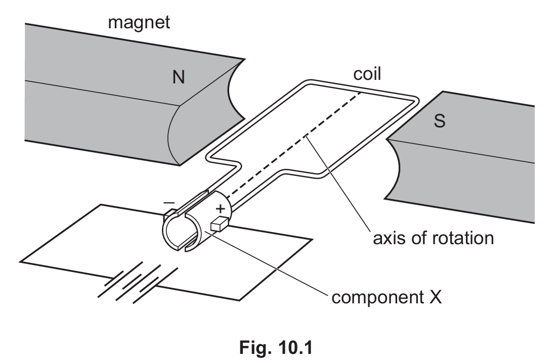
(a)(i) more turns of wire / more turns on the coil ; increase current ; stronger magnetic field
The turning effect (torque) on a coil in a magnetic field increases with the number of turns, the current flowing through the coil, and the strength of the magnetic field.
(a)(ii) split-ring commutator
The split-ring commutator is a device that reverses the direction of current through the coil every half-turn.
(a)(iii) reverses the direction of the current (in the coil) ; every half a turn
The commutator ensures that the current in the coil always flows in a direction that produces a turning force in the same rotational direction, allowing continuous rotation.
(b)(i) step-up
A step-up transformer increases the voltage for efficient long-distance transmission of electrical power.
(b)(ii) higher voltage ; means lower current (for same power transferred) ; (reference to) P = I²R or power loss proportional to current squared
By stepping up the voltage, the current in the transmission cables is reduced. Since power loss in cables is proportional to I²R, lower current significantly reduces energy losses.
(c) 46,000 turns
Using the transformer equation: Vₚ/Vₛ = Nₚ/Nₛ
230/3.6 = Nₚ/720
Nₚ = (230 × 720) ÷ 3.6 = 46,000
A step-down transformer reduces the high transmission voltage to a safer, usable voltage for domestic appliances.
Question
Most-appropriate topic codes (Cambridge IGCSE Co-ordinated Sciences 0654):
• Topic P4.5.5 — The d.c. motor (Parts a(i), a(ii) & a(iii))
• Topic P4.5.6 — The transformer (Parts b(i), b(ii), b(iii) & b(iv))
▶️ Answer/Explanation
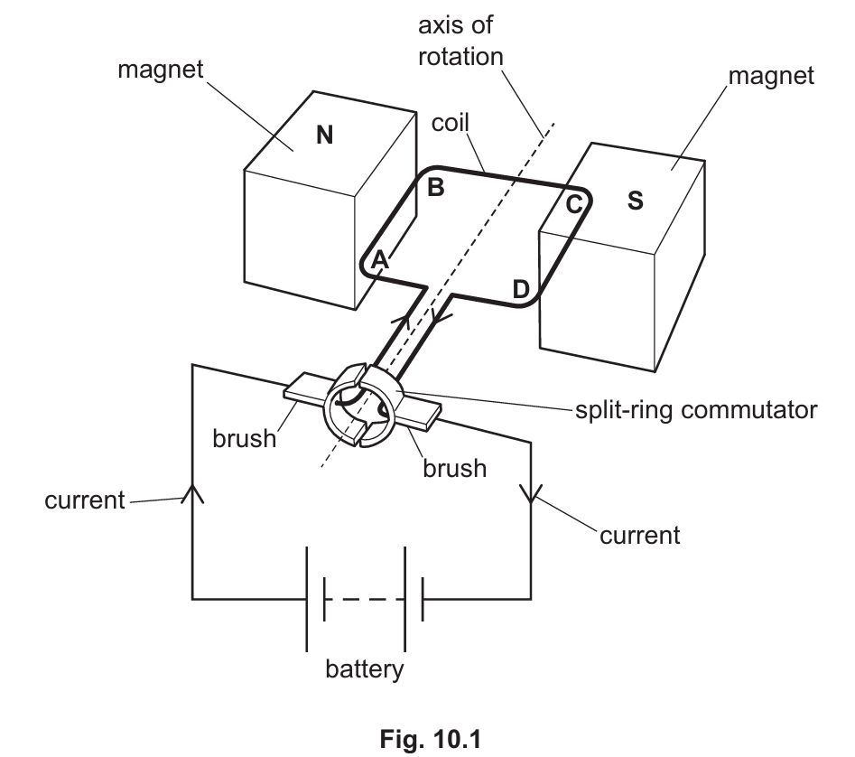
(a)(i) Why side AB experiences a force:
Side AB is a current-carrying conductor placed in a magnetic field (between the two magnets). The current flowing through the wire interacts with the magnetic field of the permanent magnets, producing a force on the wire (motor effect).
(a)(ii) How forces on AB and CD cause a turning effect:
The force on side AB is directed upwards while the force on side CD is directed downwards (or vice versa, depending on current direction). Since these forces act in opposite directions on opposite sides of the coil, they create a turning effect (moment) about the axis of rotation. This turning effect causes the coil to rotate.
(a)(iii) Role of split-ring commutator and brushes:
The split-ring commutator reverses the direction of the current in the coil every half-turn (180° of rotation). This ensures that the forces on sides AB and CD always act in the same direction relative to the rotation, maintaining continuous rotation in one direction. The brushes provide electrical contact with the rotating commutator while allowing it to spin freely.
(b)(i) Component of a basic transformer:
Soft-iron core — a transformer consists of a primary coil, a secondary coil, and a soft-iron core that links the two coils magnetically.
(b)(ii) Calculation of secondary voltage:
Using the transformer equation:
\(\frac{V_p}{V_s} = \frac{N_p}{N_s}\)
\(\frac{230}{V_s} = \frac{2500}{400}\)
\(V_s = \frac{230 \times 400}{2500} = \frac{92000}{2500} = 36.8 \, \text{V}\)
Voltage across secondary coil = 37 V (to 2 significant figures)
(b)(iii) Calculation of primary current:
For an ideal transformer (100% efficiency):
\(I_p V_p = I_s V_s\)
\(I_p \times 230 = 1.6 \times 36.8\)
\(I_p \times 230 = 58.88\)
\(I_p = \frac{58.88}{230} = 0.256 \, \text{A}\)
Current in primary coil = 0.26 A (to 2 significant figures)
(b)(iv) Assumption made:
The calculation assumes that the transformer is 100% efficient — meaning no energy is lost as heat in the coils or core, and all electrical power input is transferred to the output. In reality, transformers are not perfectly efficient due to resistance in the coils and eddy currents in the core.