Voltage and Current in a Circuit
Voltage as the Cause of Current: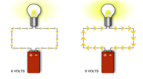
The voltage of a source (also called potential difference, p.d.) is the driving force that pushes charge around a circuit.
- Voltage provides energy to charges → this energy is transferred to components in the circuit (lamps, resistors, motors).
- Higher voltage means stronger “push” on charges, so a larger current flows (for the same resistance).
Relationship:
\(\mathrm{V = \dfrac{W}{Q}}\), where
- \(\mathrm{V}\) = voltage (volts, V)
- \(\mathrm{W}\) = energy transferred (joules, J)
- \(\mathrm{Q}\) = charge (coulombs, C)
Voltage in Series Circuits:
In a series circuit, the source voltage is shared between components.
- The sum of the voltages across each component = total voltage of the source.
- If two identical resistors are connected in series across a 12 V battery, each resistor has 6 V across it.
- The greater the resistance of a component, the larger the share of voltage it receives.
Everyday Understanding:
- A 9 V battery pushes charges around a torch circuit → the voltage provides energy for the bulb to light.
- In fairy lights (series bulbs), the supply voltage is divided among the bulbs so that each gets a smaller share, preventing overheating.
Example :
Two resistors of equal resistance are connected in series across a 12 V battery. What is the voltage across each resistor?
▶️ Answer/Explanation
Step 1: Total voltage of the source = 12 V.
Step 2: In series, voltage is shared according to resistance. Since resistances are equal, the voltage divides equally.
Step 3: Each resistor gets 6 V.
Final Answer: Voltage across each resistor = 6 V.
Use of Voltmeters
A voltmeter is an instrument used to measure the voltage (potential difference) between two points in a circuit.
General Features:
- A voltmeter is always connected in parallel with the component across which the voltage is measured, because voltage is the difference in potential between two points.
- It has a very high resistance so that it does not allow significant current to pass through it → preventing disturbance of the circuit.
- The reading is in volts (V).
Analogue Voltmeters:
- Use a pointer (needle) moving across a scale to show the voltage.
- Different ranges are available, e.g. 0–5 V, 0–10 V, 0–50 V.
- The correct range must be chosen before connecting: – Too low → risk of damaging the meter. – Too high → less sensitive reading.
- Analogue meters are useful for observing gradual changes in voltage.
Digital Voltmeters:
- Show voltage as a numerical value on a screen.
- Often more accurate and easier to read than analogue meters.

- Many digital voltmeters automatically select the correct range, or allow manual selection.
- Can measure very small voltages (mV) as well as large voltages (hundreds of volts).

Choosing the Range:
- Always start with the highest range to avoid damaging the voltmeter.
- Then reduce the range to get the most accurate measurement.
Applications:
- Checking the voltage of a household battery (e.g. 1.5 V, 9 V).
- Measuring mains supply voltage (about 230 V in many countries).
- Monitoring voltage levels in electrical circuits or devices.
Example :
A student wants to measure the voltage across a lamp connected to a 12 V supply. Which voltmeter range should be used?
▶️ Answer/Explanation
Step 1: The expected voltage is about 12 V.
Step 2: Always select a range higher than the expected value to prevent damage.
Step 3: A 0–20 V range is suitable (0–10 V would be too low).
Final Answer: The student should use the 0–20 V range.
Electromotive Force (e.m.f.)
The electromotive force (e.m.f.) of a source is the electrical work done by the source in moving a unit charge around a complete circuit.
Explanation:
When a battery or power supply drives charge through a circuit, it transfers energy to the charges.
- The e.m.f. represents the energy supplied per coulomb of charge.
Formula:
$\mathrm{e.m.f. = \dfrac{W}{Q}} $
where:
- \(\mathrm{W}\) = work done / energy supplied (joules, J)
- \(\mathrm{Q}\) = charge moved (coulombs, C)
- This definition is very similar to voltage, but specifically refers to the energy provided by the source.
Unit of e.m.f.:
- e.m.f. is measured in volts (V).
- 1 volt = 1 joule of energy supplied per coulomb of charge.
Everyday Understanding:
- A 1.5 V cell supplies 1.5 joules of energy for every coulomb of charge it moves around the circuit.
- A 12 V car battery supplies 12 joules per coulomb of charge.
Example :
A battery does 24 J of work in moving 4 C of charge around a circuit. What is the e.m.f. of the battery?
▶️ Answer/Explanation
Step 1: Use formula \(\mathrm{e.m.f. = \dfrac{W}{Q}}\).
Step 2: Substitute: \(\mathrm{e.m.f. = \dfrac{24}{4} = 6 \, V}\).
Final Answer: The battery has an e.m.f. of 6 V.
Potential Difference (p.d.)
The potential difference (p.d.) between two points in a circuit is the work done by a unit charge in passing between those two points.
Explanation:
When charge flows through a component (e.g. lamp, resistor), it loses energy as it transfers it to the component.
- The p.d. between two points measures the amount of energy transferred per coulomb of charge.
Formula:
$ \mathrm{V = \dfrac{W}{Q}}$
- where:
- \(\mathrm{V}\) = potential difference (volts, V)
- \(\mathrm{W}\) = work done / energy transferred (joules, J)
- \(\mathrm{Q}\) = charge (coulombs, C)
Unit of Potential Difference:
- P.d. is measured in volts (V).
- 1 volt = 1 joule of energy transferred per coulomb of charge.
Difference Between e.m.f. and p.d.:
- e.m.f.: Energy supplied per coulomb by the source.
- p.d.: Energy transferred per coulomb to a component in the circuit.
Everyday Understanding:
- A lamp connected across 6 V has 6 joules of energy transferred to it by each coulomb of charge.
- A phone charger supplying 5 V means that each coulomb of charge transfers 5 J of energy to the phone’s circuit.
Example :
12 J of energy is transferred when 3 C of charge passes through a resistor. Calculate the potential difference across the resistor.
▶️ Answer/Explanation
Step 1: Use formula \(\mathrm{V = \dfrac{W}{Q}}\).
Step 2: Substitute: \(\mathrm{V = \dfrac{12}{3} = 4 \, V}\).
Final Answer: The potential difference across the resistor is 4 V.