Circuit Diagrams and Components
Power Sources
![]()

- Cell: Single source of electrical energy. Provides a small voltage (e.g. 1.5 V). Symbol = one long line (positive) and one short line (negative).
- Battery: Two or more cells connected in series. Provides a higher voltage. Symbol = multiple pairs of long and short lines.
- Power supply: Alternative to batteries, provides a controlled d.c. or a.c. source.
Switch
![]()
- Used to open (off) or close (on) the circuit.
- Symbol = a break in the line with a pivoted arm that can connect.
- When open → no current flows. When closed → circuit complete, current flows.
Resistors

- Fixed resistor: Opposes current with a fixed resistance value. Symbol = rectangular box.
- Variable resistor (rheostat): Resistance can be adjusted. Symbol = rectangle with a diagonal arrow. Used to control current in circuits (e.g. dimming lights).
Heater
![]()
- Converts electrical energy into heat energy (high resistance wire).
- Symbol = rectangular box with short lines inside (to represent heating element).
Lamps (Bulbs)

- Convert electrical energy into light + heat.
- Symbol = a circle with a cross (×) inside.
- If current too high → filament may blow.
Motor
![]()
- Converts electrical energy into kinetic (rotational) energy.
- Symbol = circle with “M” inside.
Measuring Instruments

- Ammeter: Measures current. Symbol = circle with “A”. Always connected in series (low resistance).
- Voltmeter: Measures potential difference. Symbol = circle with “V”. Always connected in parallel across component (high resistance).
Fuse

- Safety device that melts if current is too high, breaking the circuit.
- Symbol = rectangle with a line through it (or sometimes a simple small box).
- Protects appliances from overheating and fire hazards.
Behaviour of Components in a Circuit
- Cell/Battery: Supplies electrical energy → higher voltage = stronger push of current.
- Switch: Controls whether current flows.
- Fixed Resistor: Reduces current, drops voltage.
- Variable Resistor: Adjusts current/voltage levels.
- Heater: Gets hot, transfers energy as heat.
- Lamp: Lights up when current flows. Brightness depends on current.
- Motor: Rotates faster if more current supplied.
- Ammeter: Shows current, connected in series.
- Voltmeter: Shows p.d., connected in parallel.
- Fuse: Breaks circuit if current too high.
Example: A battery, switch, lamp, and ammeter in series, with a voltmeter connected across the lamp.
- Battery pushes current around.
- Switch controls on/off.
- Ammeter measures the current through the lamp.
- Voltmeter measures voltage across the lamp.
- Lamp glows when switch closed.
Example :
In the circuit, the ammeter shows 0.6 A when the lamp is connected to a 6 V battery. What is the resistance of the lamp?
▶️ Answer/Explanation
Step 1: Formula: \(R = \dfrac{V}{I}\).
Step 2: Substitute: \(R = \dfrac{6}{0.6} = 10 \, \Omega\).
Final Answer: The lamp has a resistance of 10 Ω.
Circuit Diagrams with Generators and LEDs
Generator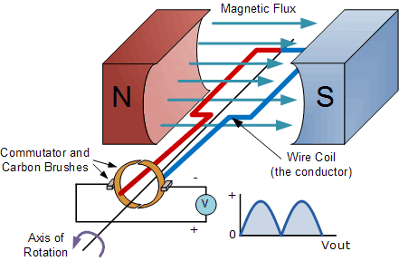
A generator converts mechanical energy (from rotation) into electrical energy.
Symbol: A circle with “G” inside (for a.c. generator, often marked with a sine wave).
- Provides an alternating current (a.c.) output in most cases (used in power stations).
- Can also be represented as a source with terminals, like a battery symbol with an a.c. label.
Behaviour in Circuit:
- Drives current around a circuit when its coil rotates in a magnetic field.
- The faster it spins, the greater the voltage and current it produces.
- Produces an output voltage that varies with time (a.c.), unlike a steady d.c. from a battery.
Light-Emitting Diode (LED)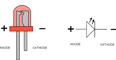
An LED is a special type of diode that emits light when current flows through it in the forward direction.
Symbol: A diode triangle with two arrows pointing outward (to show emission of light).
- Only allows current to flow in one direction (forward bias). In reverse bias, it blocks current.
Behaviour in Circuit:
- LED lights up only when connected with the correct polarity (positive to positive terminal, negative to negative).
- They require a resistor in series to limit current — otherwise they may burn out.
- Commonly used in indicators, displays, and low-energy lighting.
Interpreting Circuits
- Generator + Lamp Circuit: Generator symbol replaces the battery, providing a.c. supply to light a lamp.
- Generator + LED Circuit: LED lights up when generator’s output drives current in the forward direction. In alternating current circuits, the LED will flash on and off (only during the half-cycle when it is forward biased).
Example :
An LED is connected to an a.c. generator. Explain why the LED flashes instead of giving a steady light.
▶️ Answer/Explanation
Step 1: The generator produces alternating current → current direction reverses each half cycle.
Step 2: An LED only conducts in one direction (forward bias).
Step 3: Therefore, the LED only lights during one half of the cycle and remains off during the other half.
Final Answer: The LED flashes on and off at the frequency of the a.c. supply.