▶️ Answer/Explanation
Rules for magnetic field lines:
• Magnetic field lines emerge from the north pole and enter the south pole.
• Field lines never cross.
• Like poles repel, so field lines between two north poles must curve away from the central region.
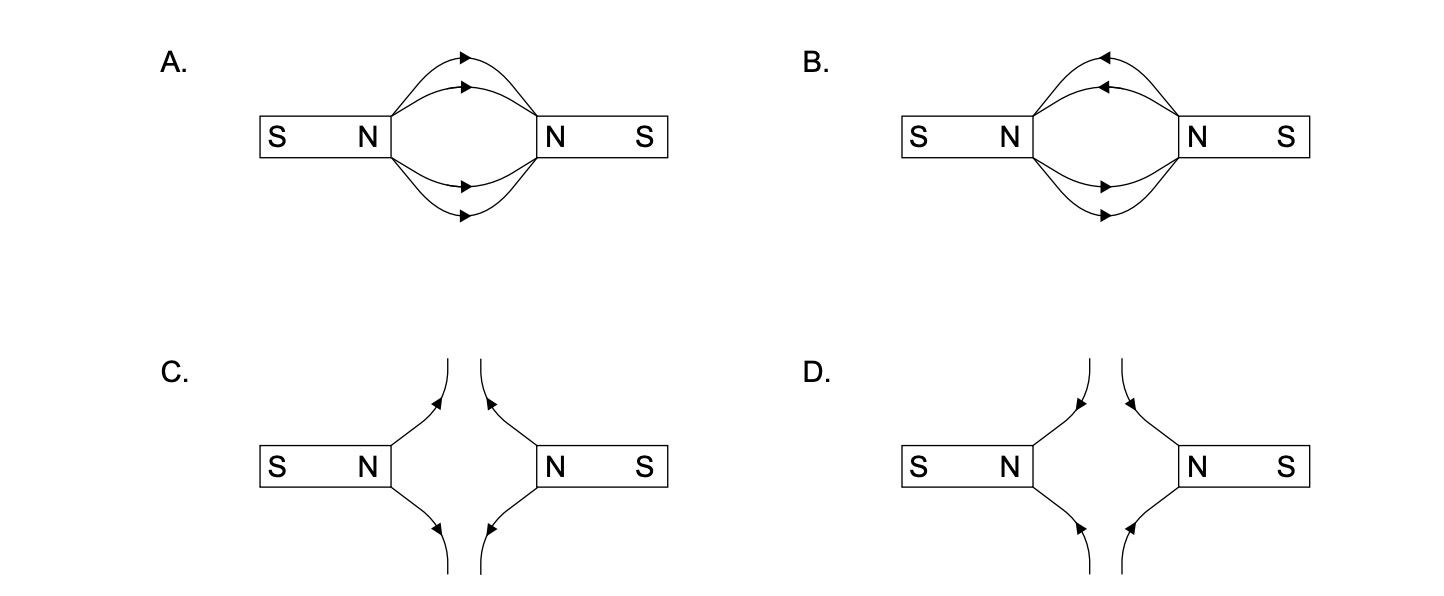
When two north poles face each other, the field lines should:
• point away from each north pole, and
• bend outward due to repulsion.
Examining the diagrams:
• Diagrams where field lines point towards a north pole are incorrect.
• Diagrams where field lines directly connect two north poles are also incorrect.
• Only diagram (C) shows field lines emerging from both north poles and curving away from each other without crossing.
✅ Answer: (C)

▶️ Answer/Explanation
Path R is undeflected, so the particle has no charge \(\Rightarrow\) neutron.
With the magnetic field into the page and the particle moving to the right, a positive charge curves upward and a negative charge curves downward.
Hence Q is a proton and S is an electron.
✅ Answer: (A)
▶️ Answer/Explanation
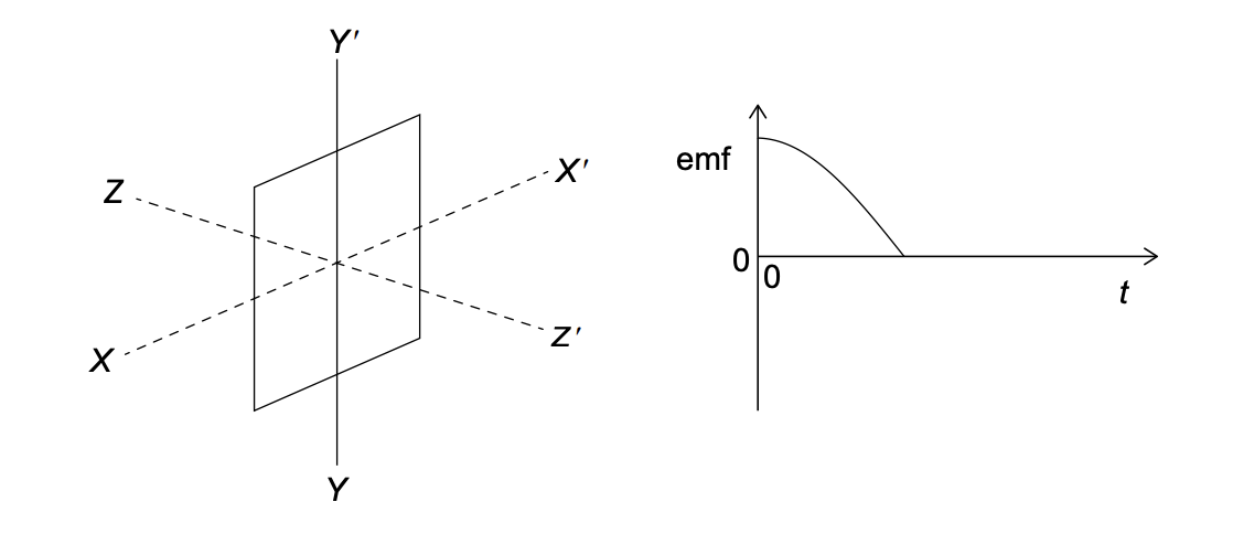
1. Analyze Initial Position:
Plane is perpendicular to \(ZZ’\) (plane is in XY). Field is along \(YY’\) (vertical).
The field lines run parallel to the plane of the coil. Flux \(\Phi = 0\).
However, the rate of change of flux is maximum when flux is zero (coil cutting lines perpendicularly). So, EMF should be maximum. The graph starts at maximum EMF. This fits.
2. Analyze Rotation Axis:
To induce EMF, flux must change.
- Rotation about \(YY’\) (axis parallel to field): Flux remains zero. No EMF. (Eliminates C, D).
- Rotation about \(XX’\) (axis perpendicular to field): The coil will turn into the field, increasing flux. This induces EMF.
3. Analyze Graph Duration:
The graph shows EMF starting at max, going to zero, and staying zero. This looks like a quarter turn (\(\pi/2\)). After \(\pi/2\), the coil is perpendicular to the field (max flux, zero EMF). If it stops there, EMF is zero. If it continues, EMF would go negative.
The graph shows a pulse corresponding to a rotation of \(\pi/2\).
✅ Answer: (A)