Question
\( \displaystyle B_R = \frac{\mu_0 I_R}{2\pi r} \),
where \(r\) is the separation between R and Z.
Calculate the emf induced in the coil.
(e)(i) Calculate the initial radius of the electron’s path.
(e)(ii) Explain the subsequent change in the radius of the electron’s path.
▶️ Answer/Explanation
(a)(i)
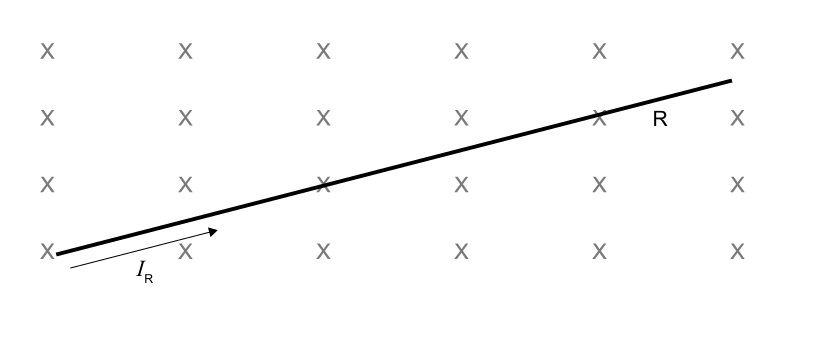
Force on a current-carrying conductor in a magnetic field: \(F = BIL\).
Force per unit length: \(\displaystyle \frac{F}{L} = BI\).
Given \(B = 0.50\ \text{T}\), \(I = 2.0\ \text{A}\):
\( \frac{F}{L} = (0.50)(2.0) = 1.0\ \text{N·m}^{-1} \)
\(\boxed{1.0\ \text{N·m}^{-1}}\)
(a)(ii)
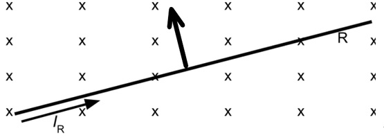
Using Fleming’s left-hand rule: current (right), magnetic field (into page) ⇒ force direction is upwards (perpendicular to both).
An arrow pointing vertically upward should be drawn on the rod in the diagram.
(b)(i)
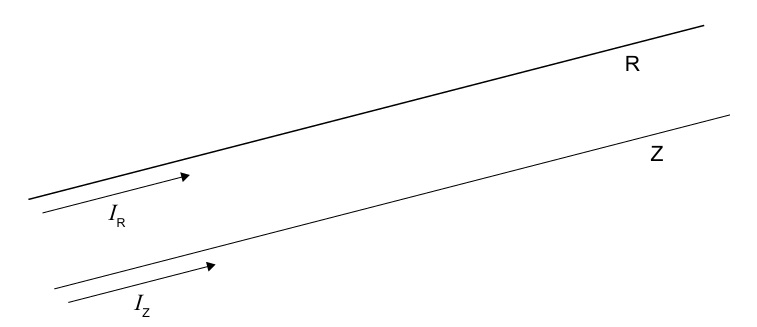
Magnetic field due to a long straight current-carrying wire:
\( B = \frac{\mu_0 I}{2\pi r} \)
Here, the field at wire Z due to current \(I_R\) in R is:
\( B_R = \frac{\mu_0 I_R}{2\pi r} \)
Derivation complete.
(b)(ii)
From \(\displaystyle \frac{F}{L} = \frac{\mu_0 I_1 I_2}{2\pi r}\), solve for \(\mu_0\):
\( \mu_0 = \frac{2\pi r (F/L)}{I_1 I_2} \)
Units: \(r\) (m), \(F/L\) (N·m\(^{-1}\)), \(I\) (A). Since N = kg·m·s\(^{-2}\):
\( [\mu_0] = \frac{\text{m} \cdot (\text{kg·m·s}^{-2}\cdot\text{m}^{-1})}{\text{A}^2} = \frac{\text{kg·m·s}^{-2}}{\text{A}^2} = \text{kg·m·s}^{-2}\text{A}^{-2} \)
\(\boxed{\text{kg·m·s}^{-2}\text{A}^{-2}}\)
(c)(i)
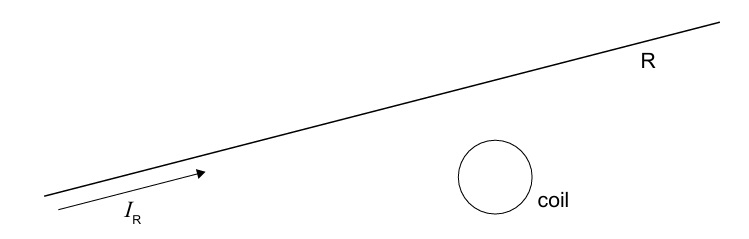
The magnetic field produced by the straight wire R at the coil’s position is constant when \(I_R\) is constant. Therefore, the magnetic flux through the coil is constant. By Faraday’s law, an emf (and hence current) is induced only when the flux is changing.
Constant flux ⇒ no induced current.
(c)(ii)
Field at coil centre: \(B = \frac{\mu_0 I}{2\pi d}\), with \(d = 0.10\ \text{m}\).
Change in current: \(\Delta I = 10.0 – 2.0 = 8.0\ \text{A}\) in \(\Delta t = 0.5\ \text{s}\).
Change in field: \(\displaystyle \Delta B = \frac{\mu_0 \Delta I}{2\pi d} = \frac{(4\pi\times10^{-7})(8.0)}{2\pi(0.10)} = 1.6\times10^{-5}\ \text{T}\).
Coil area: \(A = \pi r^2 = \pi(0.020)^2 = 1.2566\times10^{-3}\ \text{m}^2\).
Change in flux through one turn: \(\Delta \Phi = \Delta B \cdot A = (1.6\times10^{-5})(1.2566\times10^{-3}) = 2.01\times10^{-8}\ \text{Wb}\).
Total flux change for \(N = 20\) turns: \(N\Delta\Phi = 20(2.01\times10^{-8}) = 4.02\times10^{-7}\ \text{Wb}\).
Induced emf: \(\displaystyle \varepsilon = N\frac{\Delta\Phi}{\Delta t} = \frac{4.02\times10^{-7}}{0.5} = 8.04\times10^{-7}\ \text{V}\).
\(\boxed{8.0\times10^{-7}\ \text{V}}\) (to 2 s.f.)
(c)(iii)
The current in R increases ⇒ magnetic field into the page at the coil increases. By Lenz’s law, the induced current will oppose this increase by producing a field out of the page. Using the right-hand grip rule, a current flowing counterclockwise (as viewed from the wire toward the coil) produces such a field.
\(\boxed{\text{Counterclockwise (anticlockwise)}}\)
(d)
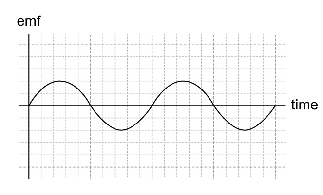
Doubling the frequency halves the period, so the sinusoidal curve on the emf–time graph should have half the horizontal period (peaks twice as close). The amplitude doubles because \(\varepsilon_{\text{max}} = NBA\omega\) and \(\omega = 2\pi f\).
Sine wave with halved period and doubled amplitude compared to original.
(e)(i)
Magnetic force provides centripetal force: \(qvB = \frac{mv^2}{r}\).
Thus \(\displaystyle r = \frac{mv}{qB}\).
Given: \(m_e = 9.11\times10^{-31}\ \text{kg}\), \(v = 9.0\times10^5\ \text{m·s}^{-1}\), \(q = 1.60\times10^{-19}\ \text{C}\), \(B = 4.0\times10^{-6}\ \text{T}\):
\( r = \frac{(9.11\times10^{-31})(9.0\times10^5)}{(1.60\times10^{-19})(4.0\times10^{-6})} \approx 1.28\ \text{m} \)
\(\boxed{1.3\ \text{m}}\) (to 2 s.f.)
(e)(ii)
The magnetic field produced by the wire decreases with distance from the wire. As the electron curves away from the wire, the field strength it experiences decreases. Since \(r \propto 1/B\), a smaller \(B\) leads to a larger radius of curvature.
Radius increases because B decreases with distance from the wire.