Question

In the circuit shown above, the switch S is initially in the open position and both capacitors are initially uncharged. Then the switch is moved to position A.
(a) Determine the current through the 20 Ω resistor immediately after the switch is moved to position A.
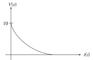
(b) Sketch a graph of voltage vs. time for the voltage across the 10 Ω resistor. After a long time the switch is moved to position B.
(c) Determine the current through the 15 Ω resistor immediately after the switch is moved to position B.
(d) Determine the amount of charge stored on the upper plate of the 20 µF capacitor after a long time.
▶️Answer/Explanation
(a) When the switch is first moved to position A the 50 µF capacitor is acting like a wire because it does not oppose the current when it is uncharged. The current through the 20 n resistor is the same as the entire left side of the circuit because it is a series circuit. Use Ohm’s law to solve for the current.
V= IR
30V =1(10 Ω +20 Ω )
I = 1. 0 A
(b) The initial voltage across the 10 n resistor can be calculated
using Ohm’s law.
V=IR
V = (I A) (10 Ω )
V = 10 V
For an RC circuit the voltage across the resistor will decrease exponentially because the current decreases exponentially as the capacitor is charging. The sketch of the voltage is shown
below.
(c) When the switch is in position A, the capacitor will continue being charged until the voltage across the 50 µF becomes 30 V, which will happen after a long time. When the switch is moved to position B, the 20 µF capacitor acts like a wire because it is uncharged. Use Ohm’s law to solve for the current through the 15 Ω resistor immediately after the switch is moved to position B.
V=lR
30 V = 1(15 Q)
1 = 2A
( d) The total charge stored on the 50 µF capacitor when the switch is at position A can be calculated using the equation
\(C=\frac{Q}{V}\)
\(50\mu F=\frac{Q}{30V}\)
Q=l,500 µC
When the switch is moved to position B, this charge will distribute between the two capacitors until the system reaches equilibrium. The voltage across each capacitor will be the same when the system is in equilibrium. Use this information and the fact that \(\Delta V=\frac{Q}{C}\) for a capacitor. Let q C be the charge on the 20 µF capacitor, which means 1,500 – q is the charge on the 50 µF capacitor.
\(\frac{1,500-q}{50}=\frac{q}{20}\)
3 0, 0 0 0 – 2 Oq = 5 Oq
30,000 = 70q
q = 429µC