WAVES
WAVE MOTION
- Mechanical waves : These waves require material medium for their propagation. For example : sound waves, waves in stretched string etc.
- Non-mechanical waves or electromagnetic waves : These waves do not require any material medium for their propagation. For example : light waves, x-rays etc.
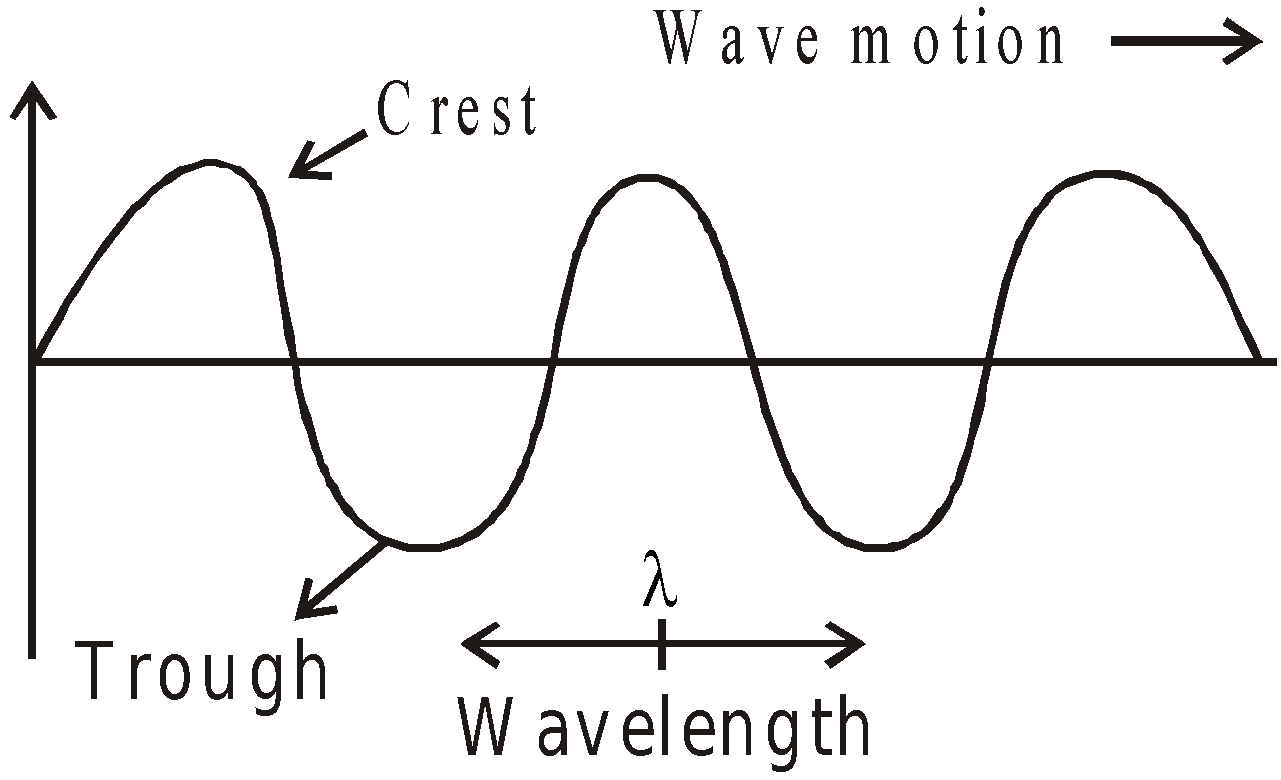
- Transverse waves : In the transverse wave, the particles of medium oscillate in a direction perpendicular to the direction of wave propagation. Waves in stretched string, waves on the water surface are transverse in nature.
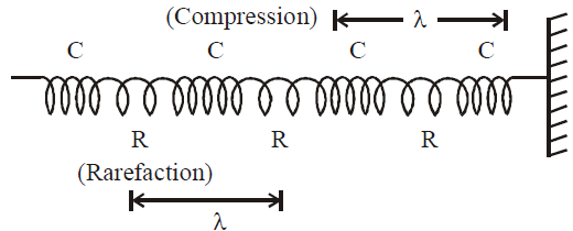
- Longitudinal waves : In longitudinal waves particles of medium oscillate about their mean position along the direction of wave propagation.
EQUATION OF A HARMONIC WAVE


- Phase difference of 2π radian is equivalent to a path difference λ and a time difference of period T.
- Phase difference =
 × path difference

- Phase difference =
 × time difference

- Time difference =
 × path difference

SPEED OF TRANSVERSE WAVES
- The speed of transverse waves in solid is given by

- The speed of transverse waves on stretched string is given by

SPEED OF LONGITUDINAL WAVES


SPEED OF SOUND IN A GAS

POWER AND INTENSITY OF WAVE MOTION
PRINCIPLE OF SUPERPOSITION OF WAVES
INTERFERENCE OF WAVES
- The ratio of maximum and minimum intensities in any interference wave form.

- Average intensity of interference in wave form :
Put the value of Imax and Imin
- Condition of maximum contrast in interference wave form
- For a wave, v = f λ
- The wave velocity of sound in air

- Particle velocity is given by
 . It changes with time. The wave velocity is the velocity with which disturbances travel in the medium and is given by
 .
. - When a wave reflects from denser medium the phase change is π and when the wave reflects from rarer medium, the phase change is zero.
- In a tuning fork, the waves produced in the prongs is transverse whereas in the stem is longitudinal.
- A medium in which the speed of wave is independent of the frequency of the waves is called non-dispersive. For example air is a non-dispersive medium for the sound waves.
- Transverse waves can propagate in medium with shear modulus of elasticity e.g., solid whereas longitudinal waves need bulk modulus of elasticity hence can propagate in all media solid, liquid and gas.
ENERGY TRANSPORTED BY A HARMONIC WAVE ALONG A STRING

BEATS
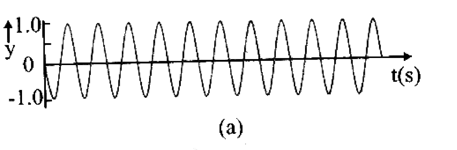
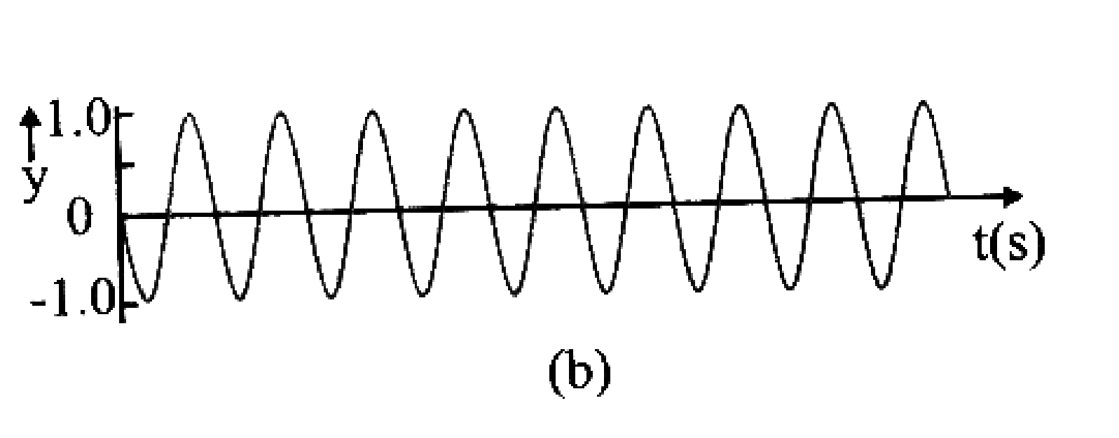
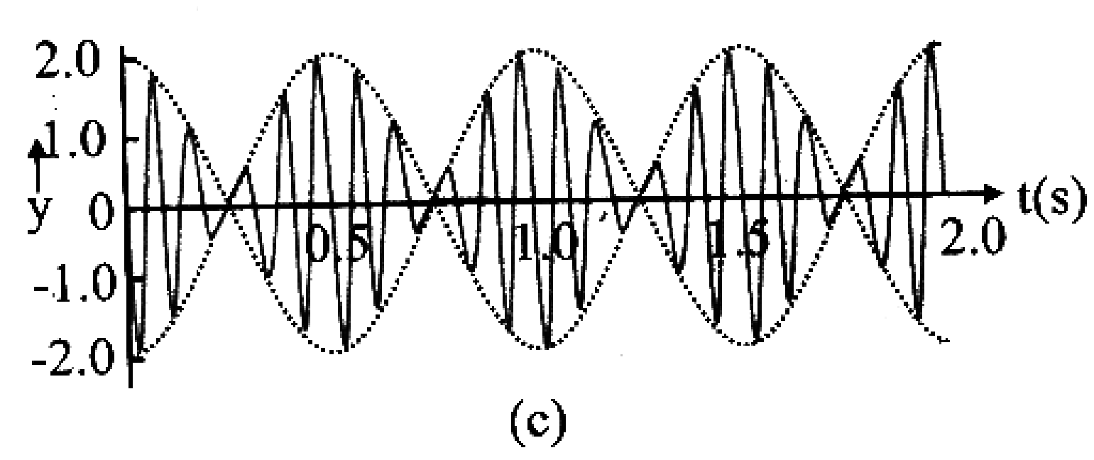
- Abeat = 2A cos 2πnAt, amplitude of resultant wave varies periodically as frequency
- Since intensity is proportional to amplitude i.e.,


FILING/LOADING A TUNING FORK
- When a tuning fork of frequency ν produces Δν beats per second with a standard tuning fork of frequency ν0, then

- If the beat frequency decreases or reduces to zero or remains the same on loading the unknown fork with a little wax, then

DOPPLER EFFECT
- When source is in motion and observer at rest
- when source moving towards observer
- when source moving away from observer
- When source is at rest and observer in motion
- when observer moving towards source
- when observer moving away from source and
V0 = velocity of observer.
- When source and observer both are in motion
- If source and observer both move away from each other.
- If source and observer both move towards each other.
- When the wind blows in the direction of sound, then in all above formulae V is replaced by (V + W) where W is the velocity of wind. If the wind blows in the opposite direction to sound then V is replaced by (V – W).
- The motion of the listener causes change in number of waves received by the listener and this produces an apparent change in frequency.
- The motion of the source of sound causes change in wavelength of the sound waves, which produces apparent change in frequency.
- If a star goes away from the earth with velocity v, then the frequency of the light emitted from it changes from ν to ν’.
If wavelength of the observed waves decreases then the object from which the waves are coming is moving towards the listener and vice versa.
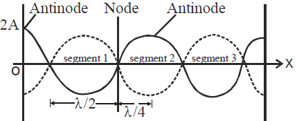
STATIONARY OR STANDING WAVES
- As = 0, when cos kx = 0 i.e., kx = π/2, 3π/2…………
i.e., x = λ/4, 3λ/4……………….[as k = 2π/λ]
- As is maximum, when cos kx is max
- The distance between node and antinode is λ/4 (see figure)
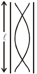
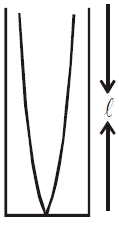
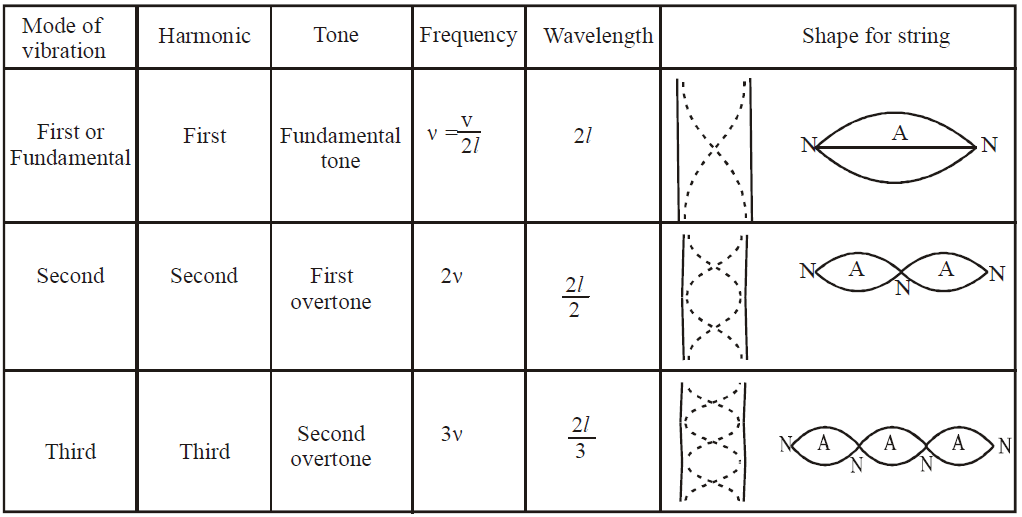
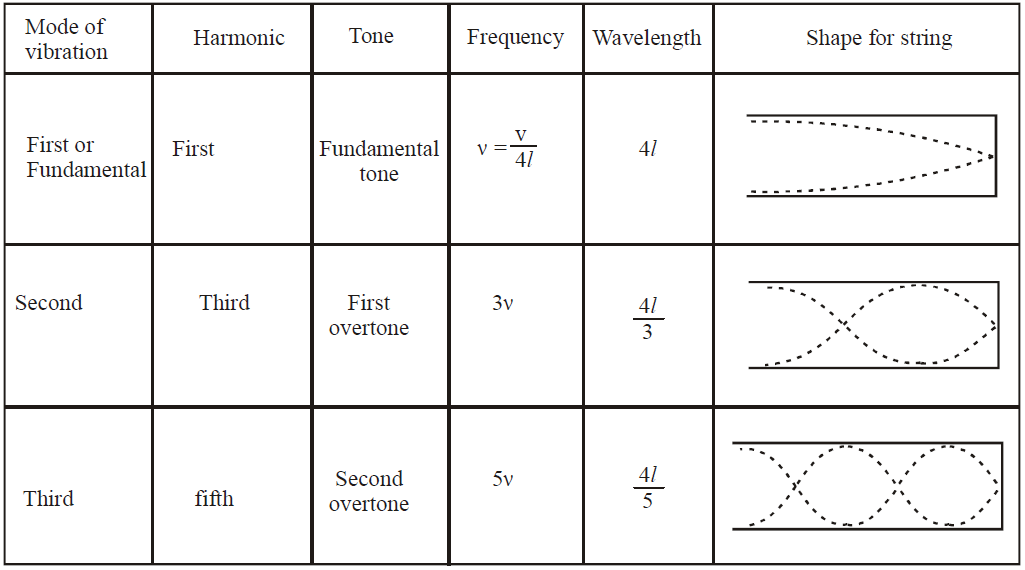
- When a string vibrates in one segment, the sound produced is called fundamental note. The string is said to vibrate in fundamental mode.
- The fundamental note is called first harmonic, and is given by
 , where v = speed of wave.
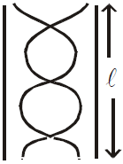
 - If the fundamental frequency be
 then
then  ,
,  ,
,  … are respectively called second third, fourth … harmonics respectively.
 - If an instrument produces notes of frequencies
 …. where
  ….., then
  is called first overtone,
  is called second overtone,
  is called third overtone … so on.
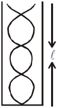
 - Harmonics are the integral multiples of the fundamental frequency. If ν0 be the fundamental frequency, then nν0 is the frequency of nth harmonic.
- Overtones are the notes of frequency higher than the fundamental frequency actually produced by the instrument.
- In the strings all harmonics are produced.
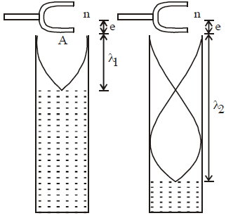
STATIONARY WAVES IN AN ORGAN PIPE


- For closed organ pipe : l is replaced by l + e where e = 0.3D, D is the diameter of the tube.
- For open organ pipe : l is replaced by l + 2e where e = 0.3D
RESONANCE TUBE
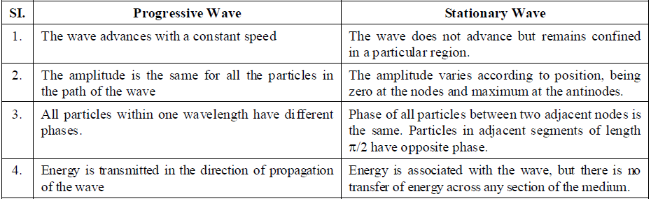
COMPARISON OF PROGRESSIVE (OR TRAVELLING) AND STATIONARY (OR STANDING) WAVE
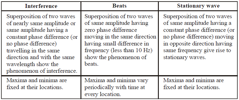
COMPARATIVE STUDY OF INTERFERENCE, BEATS AND STATIONARY WAVE
CHARACTERISTICS OF SOUND
- Pitch depends on frequency
- loudness depends on intensity
- quality depends on the number and intensity of overtones
ACOUSTICS
- Electro acoustics. This branch deals with electrical sound production with music.
- Musical acoustics. This branch deals with the relationship of sound with music.
- Architectural acoustics. This branch deals with the design and construction of buildings.
REVERBERATION
α1 , α2 …. are their respective absorption coefficient.
SHOCK WAVES
INTENSITY OF SOUND
LISSAJOUS FIGURES
- ratio of frequencies or time periods of two waves
- ratio of amplitude of two waves
- phase difference between two waves.
Superposition of Waves
When two or more waves simultaneously pass through a point, the disturbance at the point is given by the sum of the disturbances each wave would produce in absence of the other wave(s).
The displacement of the particles, if the first wave alone were travelling, may be written as
\(y_1=f_1(t-x/v)\)
and the displacement if the second wave alone were travelling may be written as
\(y_2=f_2(t+x/v)\)
\(y=y_1+y_2 =y_1=f_1(t-x/v) + y_2=f_2(t+x/v)\)

A series of snapshots that show two pulses traveling in opposite directions along a stretched string.The superposition principle applies as the pulses move through each other.
Polarization
Polarization is a phenomenon peculiar to transverse waves. Longitudinal waves such as sound cannot be polarized. Light and other electromagnetic waves are transverse waves made up of mutually perpendicular, fluctuating electric and magnetic fields. In the diagram below an EM wave is propagating in the x-direction, the electric field oscillates in the xy-plane, and the magnetic field oscillates in the xz-plane. A line traces out the electric field vector as the wave propagates.
An unpolarized electromagnetic wave traveling in the x-direction is a superposition of many waves. For each of these waves the electric field vector is perpendicular to the x-axis, but the angle it makes with the y-axis is different for different waves. For unpolarized light traveling in the x-direction Ey and Ez are randomly varying on a timescale that is much shorter than that needed for observation.
Unpolarized light: Natural light is, in general, unpolarized.
For a linearly polarized electromagnetic wave traveling in the x-direction, the angle the electric field makes with the y-axis is unique.
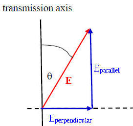
An ideal polarizer is a material that passes only EM waves for which the electric field vector is parallel to its transmission axis. The electric field is a vector and can be written in terms of the components parallel and perpendicular to the polarizer’s transmission axis.
E = Eparallel + Eperpendicular.
An ideal polarizer passes Eparallel and absorbs Eperpendicular.
If E0 is the incident field vector and the angle between E0 and the transmission axis is θ, then the magnitude of transmitted field vector is E0 cosθ and its direction is the direction of the transmission axis. The intensity I of an electromagnetic wave is proportional to the square of the magnitude of the electric field vector. We therefore have
Itransmitted = I0 cos2θ.
This is called the law of Malus. If θ = 90o the transmitted intensity is zero.
The lines indicate the direction of the transmission axis.
When unpolarized light passes through a polarizer, the intensity is reduced by a factor of ½. The average of cos2θ, averages over all angles θ is ½.
Itransmitted = I0<cos2θ>all angles = ½I0.
Problem:
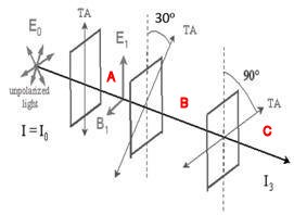
A beam of unpolarized light of intensity I0 passes through a series of ideal polarizing filters with their transmission axis turned to various angles, as shown in the figure.
(a) What is the light intensity (in terms of I0) in regions A, B, and C?
(b) If we remove the middle filter, what will be the light intensity at point C?
Solution:
- Reasoning:
When unpolarized light passes through a polarizer, the intensity is reduced by a factor of ½. The transmitted light is polarized along the axis of the polarizer.
When polarized light of intensity I0 is incident on a polarizer, the transmitted intensity is given by I = I0cos2θ, where θ is the angle between the polarization direction of the incident light and the axis of the filter. The transmitted light is polarized along the axis of the polarizer. - Details of the calculation:
In this problem we have 3 polarizing filters. For the second polarizer θ = 30o between the polarization direction of the light incident of the filter and the axis of the filter. For the third polarizer θ = 90o – 30o = 60o between the polarization direction of the light incident of the filter and the axis of the filter.
We then have that:
(a) In region A the intensity is I0/2 and the light is polarized along the vertical direction.
In region B the intensity is (I0/2)cos230o, = 0.375 I0, and the light is polarized along the axis of the second polarizer.
in region C the intensity is (0.375 I0)cos260o = 0.0938 I0 and the light is horizontally polarized.
(b) If we remove the middle filter, for the last filter we now have that θ = 90o. Thus I = 0.
It is important to visualize the fact that adding the middle filter increases the transmitted intensity!
This “paradoxical” effect is a signature of wave phenomena in general.
There are different polarization mechanisms. The most common method of producing polarized light is to use polaroid material, made from chains of organic molecules, which are anisotropic in shape. Light transmitted is linearly polarized perpendicular to the direction of the chains. The transmission axis is perpendicular to the chains.
A polarizer produces linearly polarized light. It is often convenient to orient the transmission axis of a polarizer vertically or horizontally to produce light with vertical or horizontal linear polarization.
Vertical and horizontal polarization
Polarization by reflection:
 When unpolarized light is incident on a boundary between two dielectric surfaces, for example on an air-water boundary, then the reflected and transmitted components are partially polarized. The reflected wave is 100% linearly polarized when the incident angle is equal to an angle called the Brewster angle.
For water this angle is is ~53o with respect to the normal or 37o with respect to the water surface.
For are considerable angular range around the Brewster angle the reflected light is highly polarized in the horizontal direction.