Essential Idea:
The majority of electricity generated throughout the world is generated by machines that were designed to operate using the principles of electromagnetic
induction.
Understandings:
- Electromotive force (emf)
- Magnetic flux and magnetic flux linkage
- Faraday’s law of induction
- Lenz’s law
Applications and Skills:
- Describing the production of an induced emf by a changing magnetic flux and within a uniform magnetic field
- Solving problems involving magnetic flux, magnetic flux linkage and Faraday’s law
- Explaining Lenz’s law through the conservation of energy
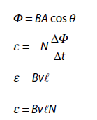
Data booklet reference:
ELECTROMAGNETIC INDUCTION
THE EXPERIMENTS OF FARADAY AND HENRY
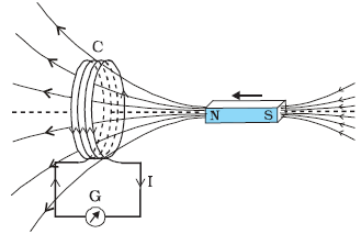
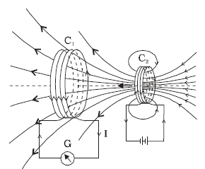
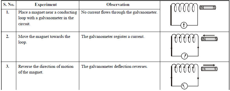
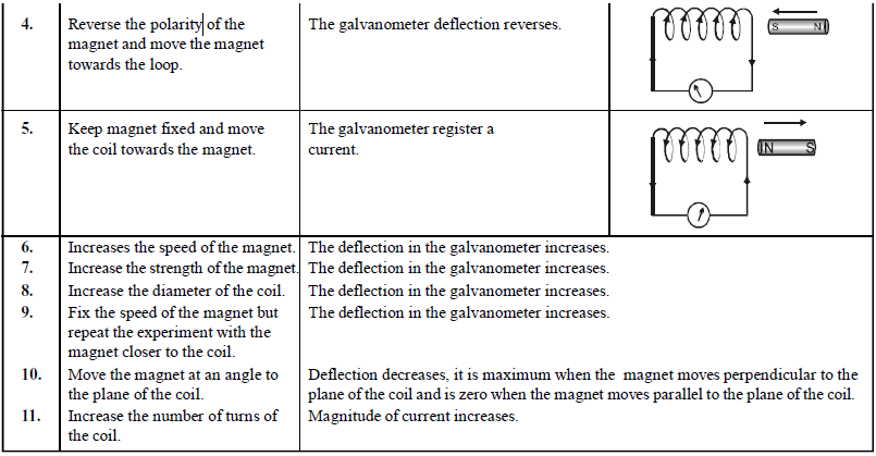
The discovery and understanding of electromagnetic induction are based on a long series of experiments carried out by Faraday and Henry. These experiments are illustrated by the following figures.
When the bar magnet is pushed towards the coil, the pointer in the galvanometer G deflects.
Current is induced in coil C1 due to motion of the current carrying coil C2
MAGNETIC FLUX
The number of magnetic lines of force crossing a surface is called magnetic flux linked with the surface.
It is represented by .
.
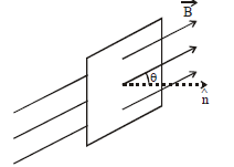
Magnetic flux 
where B is strength of magnetic field, A is area of the surface and θ is the angle which normal to the area (unit area vector) makes with the direction of magnetic field.
The S.I. unit of magnetic flux is weber which is the amount of magnetic flux over an area of 1 m2 held normal to a uniform magnetic field of one tesla.
The c.g.s. unit of φ is maxwell.
1 weber = 108 maxwell.
FARADAY’S LAW OF ELECTROMAGNETIC INDUCTION
Whenever the number of magnetic lines of force (flux) linked with any closed circuit change, an induced current flows through the circuit which lasts only so long as the change lasts. An increase in the number of lines of force produces an inverse current, while a decrease of such lines produces a direct current.
The induced emf is equal to the negative rate of change of magnetic flux.
i.e. 
The -ve sign shows that the induced emf opposes the change in magnetic flux (Lenz’s law).
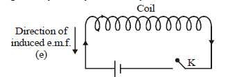
LENZ’S LAW
The direction of induced e.m.f. is given by Lenz’s law. According to this law, the direction of induced e.m.f. in a circuit is always such that it opposes the every cause which produces it.
Thus, 
Lenz’s law is in accordance with the principle of conservation of energy. Infact, work done in moving the magnet w.r.t. the coil changes into electric energy producing induced current.
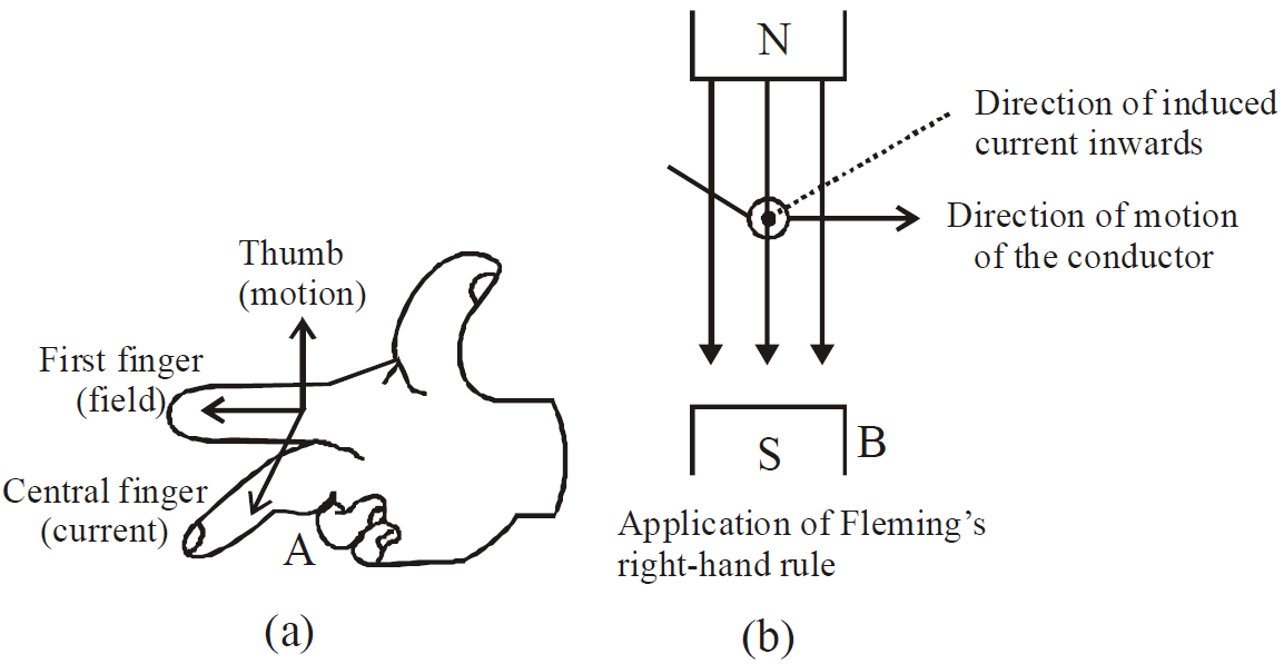
There is also another law for finding the direction of induced current. This is Fleming’s right hand rule. According to this rule, if we stretch the right-hand thumb and two nearby fingers perpendicular to one another such that the first finger points in the direction of magnetic field and the thumb in the direction of motion of the conductor, then the middle finger will point in the direction of the induced current.
Total flow of charge due to change of flux (Δφ):
METHODS OF INDUCING E.M.F.
As is known, e.m.f. is induced in a circuit only when amount of magnetic flux linked with the circuit changes. As φ = BA cos θ, therefore three methods of producing induced e.m.f. :
- By changing B
- By changing A
- By changing θ (orientation of the coil)
When a conductor of length l moves with a velocity v in a magnetic field of strength B so that magnetic flux linked with the circuit changes, the e.m.f. induced (ε) is given by
ε = B l v.
INDUCED E.M.F. AND ITS DIRECTION
Case (i) In conducting rod
The induced e.m.f. is generated because of rotation of a conducting rod in a perpendicular magnetic field
where f = frequency of rotation and
A = πr2, where r is the radius of circle in which this rod moves, hence r = l.
ω = angular velocity, l = length of conducting rod.
ω = angular velocity, l = length of conducting rod.
Case (ii) In disc
Induced e.m.f generated in a disc rotating with a constant angular velocity in a perpendicular magnetic field
where A = area of disc = πr2, r = radius of disc,
ω = angular velocity of disc.
ω = angular velocity of disc.
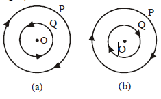
Case (iii) In two coils
When two coils are arranged as shown in the figure
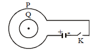
- if key K is closed then current in P will flow in clockwise direction and consequently induced current in Q will flow in anticlockwise direction. (see fig.a)
- when key K is opened then current in P falls from maximum to zero and consequently induced current in Q will flow in clockwise direction. (see fig.b)
Case (iv) In three coils arranged coaxially
Three coils P, Q and R are arranged coaxially as shown in figure. Equal currents are flowing in coils P and R . Coils Q and R are fixed. Coil P is moved towards Q. The induced current in Q will be in anti-clockwise direction so that it may oppose the approach of P according to Lenz’s law. As the face of P towards Q is a south pole hence plane of Q towards P will also be a south pole.
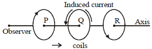
As there is no relative motion between Q and R, hence no current is induced in Q due to R.
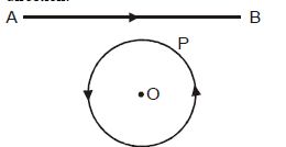
Case (v) Current increases in straight conductor
When current in the straight conductor is increased then
- the direction of induced current in the loop will be clockwise so that it may oppose the increase of magnetic flux in the loop in downward direction.
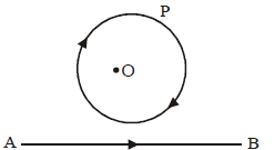
- the direction of induced current in the loop will be anti-clockwise so that it may oppose the increase of magnetic flux in the loop in upward direction.
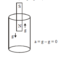
Case (vi) Magnet dropped freely in long vertical copper tube
The resistance of copper tube is quite negligible and hence maximum induced current are generated in it due to the motion of the magnet. Due to these induced current the motion of magnet is opposed to maximum. Consequently the acceleration of the magnet will be zero (a = g – g = 0).
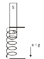
Case (vii) Magnet dropped freely into a long solenoid of copper wire
The resistance of copper solenoid is much higher than that of copper tube. Hence the induced current in it, due to motion of magnet, will be much less than that in the tube. Consequently the opposition to the motion of magnet will be less and the magnet will fall with an acceleration (a) less than g. (i.e. a < g).
Case (viii) Motional EMF
Induced emf in a conducting rod moving perpendicular through a uniform magnetic field as shown
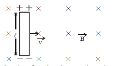
The induced emf produced across the rod
This is also called motional emf and it develops when a metal rod cuts magnetic lines of force.
Special case : If the rod moves in the magnetic field making an angle θ with it, then induced emf  .
.
COMMON DEFAULT
🗴 Incorrect. When there is no change in magnetic flux no induced current is produced.
✓ Correct. Consider the case (viii) discussed above. There is no change in the magnetic flux through the rod, still induced emf is produced.
Case (ix) A straight conductor (slider) moving with velocity v on a U shaped wire placed in a uniform magnetic field.
The induced current produced is 
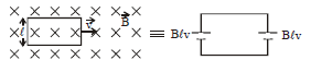
Case (x) When a rectangular loop perpendicular to the magnetic field is pulled out, then forces  and
and being equal and opposite cancel out.
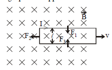
Power required to move the loop out
P= F2 × v 
Case (xi) The magnet is stationary and the loop is moving towards the magnet.
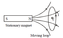
The induced emf or current I is shown which is in accordance to Lenz’s law. In this case the magnetic force causes the charge to move. We know that if a charged particle is in motion in a field it experiences a magnetic force. This is because when charged particle moves it creates its own magnetic field which interacts with the existing magnetic field.
Case (xii) The magnet is moving towards the loop which is stationary.
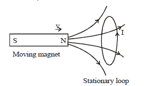
The induced emf or current I is shown which is in accordance to Lenz’s law. Here the varying magnetic field at the location of loop (due to the movement of magnet) creates an electric field.
We should remember certain points regarding the induced electric field produced due to changing magnetic field.
- Induced electric field lines form closed loops (different from the electric field lines used to depict electric field produced due to charges)
- Induced electric field is non-conservative in nature (again a difference from the electric field produced by electric charges)
Mathematically, 
Note:
- An emf is induced in a circuit where the magnetic flux is changing even if the circuit is open. But obviously no current will flow. If we close the circuit, the current will start flowing.
- In a loop moving in a uniform magnetic field, when the loop remains in the field, the net emf induced is zero.
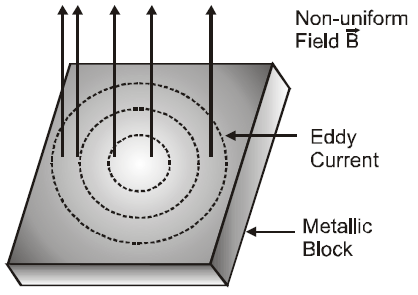
EDDY CURRENTS
The induced circulating currents produced in a metal itself due to change in magnetic flux linked with the metal are called eddy currents. These currents were discovered by Foucault, so they are also known as Foucault Currents.
The direction of eddy currents is given by Lenz’s law.
Eddy currents produced in a metallic block moving in a non-uniform magnetic field is shown in fig.
APPLICATIONS OF EDDY CURRENT
Like friction, eddy currents are helpful in some fields and have to be increased, while in some other fields they are undesirable and have to be minimised.
- Dead beat galvanometer
- Energy meter
- Speedometer
- Electric brakes
- Single phase AC motor
- Induction furnace
- Diathermy
Note:- In a moving coil galvanometer, damping is necessary to avoid oscillation of display needle. This is brought into practice with the help of eddy currents. The winding of the coil of galvanometer is done on a metallic frame. When the coil rotates the magnetic flux linked with the metallic frame changes due to which eddy currents are developed which oppose the rotation of the coil. This is called dead beat galvanometer.
SELF INDUCTANCE AND MUTUAL INDUCTANCE
SELF INDUCTANCE
The property of a coil by virtue of which the coil opposes any change in the strength of the current flowing through it, by inducing an e.m.f. in itself is called self inductance.
When a current I flows through a coil, the magnetic flux φ linked with the coil is φ = LI, where L is coefficient of self inductance of the coil.
On differentiating, we get
If dI / dt = 1; L = – e.
Hence coefficient of self inductance of a coil is equal to e.m.f. induced in the coil when rate of change of current through the same coil is unity. Coefficient of self induction of a coil is also defined as the magnetic flux linked with a coil when 1 ampere current flows through the same coil.
The value of L depends on geometry of the coil and is given by
where l is length of the coil (solenoid), N is total number of turns of solenoid and A is area of cross section of the solenoid.
The S.I. unit of L is henry. Coefficient of self induction of a coil is said to be one henry when a current change at the rate of 1 ampere/sec. in the coil induces an e.m.f. of one volt in the coil.
KEEP IN MEMORY
- Energy stored in a coil (inductor) =

where L is the self-inductance and i current flowing through the inductor.
The energy stored in the magnetic field of the coil.
- The self inductance is a measure of the coil to oppose the flow of current through it. The role of self-inductance in an electrical circuit is the same as that of the inertia in mechanics. Therefore it is called electrical inertia.
- The magnetic energy density (energy stored per unit volume) in a solenoid

MUTUAL INDUCTANCE
Mutual induction is the property of two coils by virtue of which each opposes any change in the strength of current flowing through the other by developing an induced e.m.f.
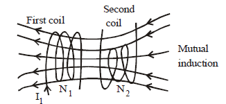
Coefficient of mutual inductance (M) of two coils is said to be one henry, when a current change at the rate of 1 ampere/sec. in one coil induces an e.m.f. of one volt in the other coil. The value of M depends on geometry of two coils, distance between two coils, relative placement of two coils etc.
The coefficient of mutual inductance of two long co-axial solenoids, each of length l, area of across section A, wound on an air core is … (1)
… (1)
where N1 and N2 are total number of turns of the two solenoids.
The mutual inductance M is defined by the equation
N2φ2 = MI1
N2φ2 = MI1
where I1 is the current in coil 1, due to which flux φ2 is linked with each turn of secondary coil.
Now we can calculate, e.m.f. e2 induced in secondary by a changing current in first coil. From Faraday‘s law
If  …(2)
…(2)
The two definitions for M defined by equations (1) and (2) are equivalent. We can express these two equations in words as :
- M is numerically equal to the flux-linkage in one circuit, when unit current flows through the other. (we use this definition to calculate M)
- M is numerically equal to the e.m.f. induced in one circuit, when the current changes in the other at the rate of one ampere in each second. (it is used to describe the mutual behavior of two circuits).
For a pair of coils, M12 = M21 = μ0 N1 N2 A/, when wound on one another.
KEEP IN MEMORY
- Coefficient of self inductance of two coils in series
The effective self inductance is Ls = L1 + L2
If M is the coefficient of mutual inductance between the two coils when they have flux linkage in the same sense,then L = L1 + L2 + 2M
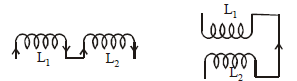
And for flux linkage in opposite direction
L = L1 + L2 – 2M
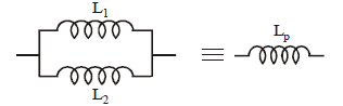
- Coefficient of self inductance of two coils in parallel
- The coefficient of coupling between two coils having self inductance L1 & L2 and coefficient of mutual inductance M is

- Generally the value of K is less than 1.
- If K is 1, then the coupling of two coils is tight while if K < 1, then coupling is loose.
- Inductance is pure geometrical factor,and is independent of current or applied e.m.f.
- If the angle between the axis of two closely placed coil is θ then

AC GENERATOR/DYNAMO/ALTERNATOR
An electrical machine used to convert mechanical energy into electrical energy is known as AC generator/alternator or dynamo.
PRINCIPLE
It works on the principle of electromagnetic induction, i.e., when a coil is rotated in uniform magnetic field, an induced emf is produced in it.
WORKING
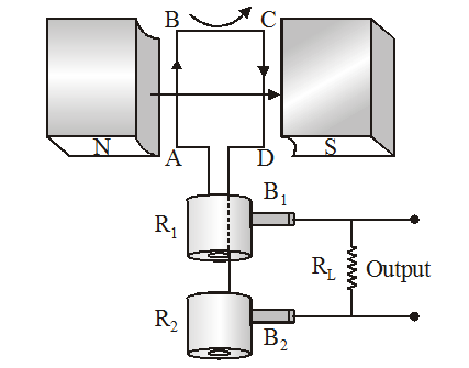
When the armature coil ABCD rotates in the magnetic field provided by the strong field magnet, it cuts the magnetic lines of force. Thus the magnetic flux linked with the coil changes and hence induced emf is set up in the coil. The direction of the induced emf or the current in the coil is determined by the Fleming’s right hand rule.
The current flows out through the brush B1 in one direction of half of the revolution and through the brush B2 in the next half revolution in the reverse direction. This process is repeated. Therefore, emf produced is of alternating nature.
DC MOTOR
A D.C. motor converts direct current energy from a battery into mechanical energy of rotation.
PRINCIPLE
It is based on the fact that when a coil carrying current is held in a magnetic field, it experiences a torque, which rotates the coil.
WORKING
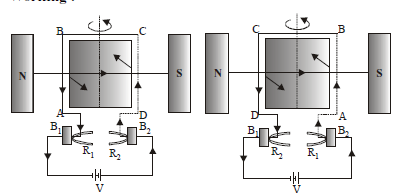
The battery sends current through the armature coil in the direction shown in fig. Applying Fleming’s left hand rule, CD experiences a force directed inwards and perpendicular to the plane of the coil. Similarly, AB experiences a force directed outwards and perpendicular to the plane of the coil. These two forces being equal, unlike and parallel form a couple. The couple rotates the armature coil in the anticlockwise direction. After the coil has rotated through 180°, the direction of the current in AB and CD is reversed, fig. Now CD experiences an outward force and AB experiences an inward force. The armature coil thus continues rotating in the same i.e., anticlockwise direction.
EFFICIENCY OF THE D.C. MOTOR
Since the current I is being supplied to the armature coil by the external source of e.m.f. V, therefore,
Input electric power = VI
According to Joule’s law of heating,
Power lost in the form of heat in the coil = I2 R
If we assume that there is no other loss of power, then
Power converted into external work
i.e., Output mechanical power = VI – I2 R = (V – IR) I = EI
∴ Efficiency of the d.c. motor
or 
USES OF D.C MOTOR
- The D.C. motors are used in D.C. fans (exhaust, ceiling or table) for cooling and ventilation.
- They are used for pumping water.
- Big D.C. motors are used for running tram-cars and even trains.